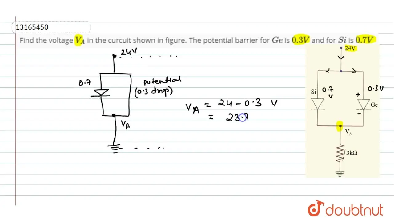
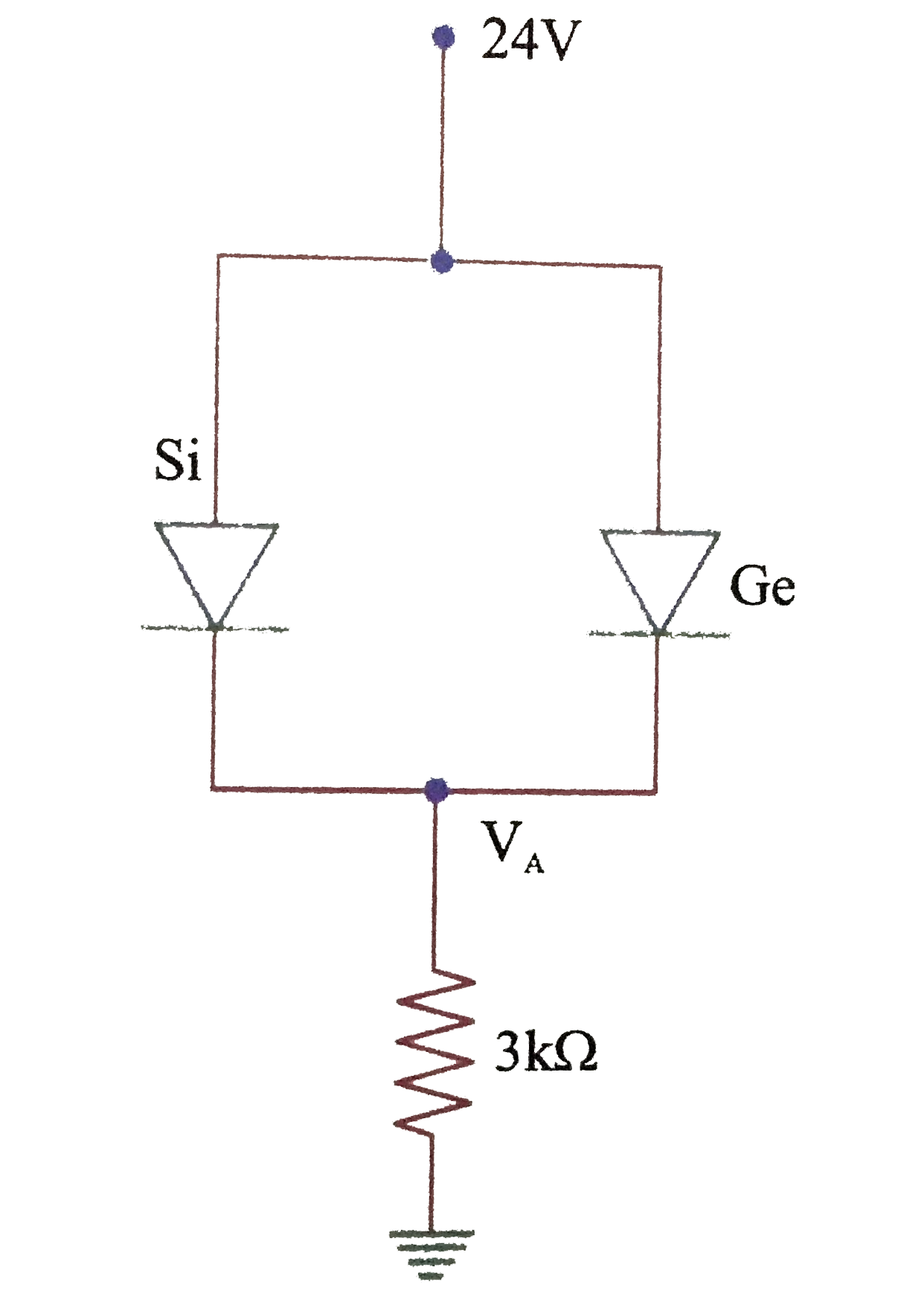
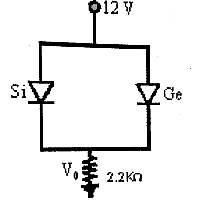
Find the voltage in the curcuit shown in figure. The potential barrier for is and for is
 .
.
Video Solution
Text Solution
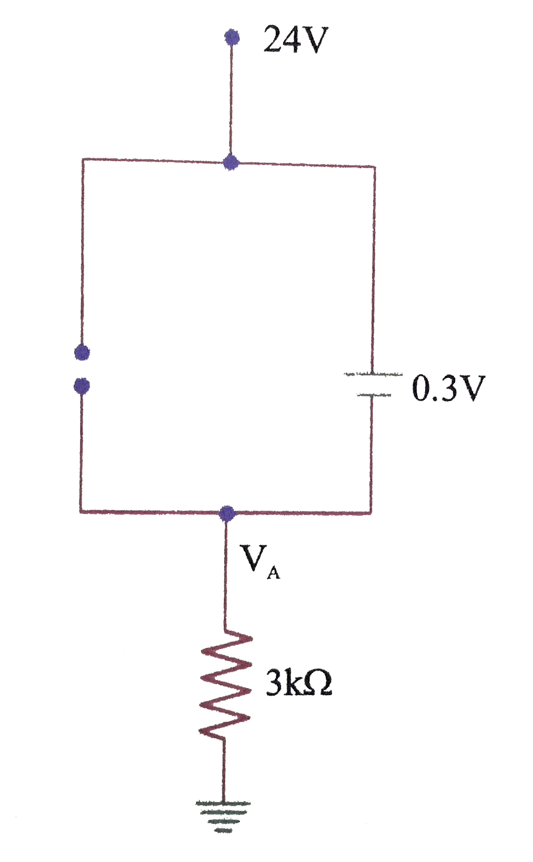
In the situation given, germanium diode will turn on first because potential barrier for germanium is smaller. The silicon diode will not get the opportunity to flow the current and so remains in open circuit. The equivalent circuit is as in figure.
.
|
Updated on:21/07/2023
Related Playlists
- BOOK - NARAYNACHAPTER - SEMI CONDUCTOR DEVICESEXERCISE - C.U.Q155videos
SEMI CONDUCTOR DEVICES
- BOOK - NARAYNACHAPTER - SEMI CONDUCTOR DEVICESEXERCISE - Level-I (C.W)21videos
SEMI CONDUCTOR DEVICES
- BOOK - NARAYNACHAPTER - RAY OPTICS AND OPTICAL INSTRAUMENTS EXERCISE - EXERCISE- 4 One or more than one correct answer type13videos
RAY OPTICS AND OPTICAL INSTRAUMENTS
- BOOK - NARAYNACHAPTER - SEMICONDUCTOR ELECTRONICSEXERCISE - ADDITIONAL EXERCISE (ASSERTION AND REASON TYPE QUESTIONS :)19videos
SEMICONDUCTOR ELECTRONICS
Similar Questions
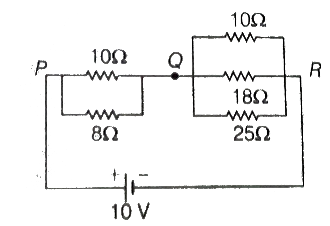
Find VP−VQ in the circuit shown in figure.
 View Solution
Find the current I & voltage V in the circuit shown.
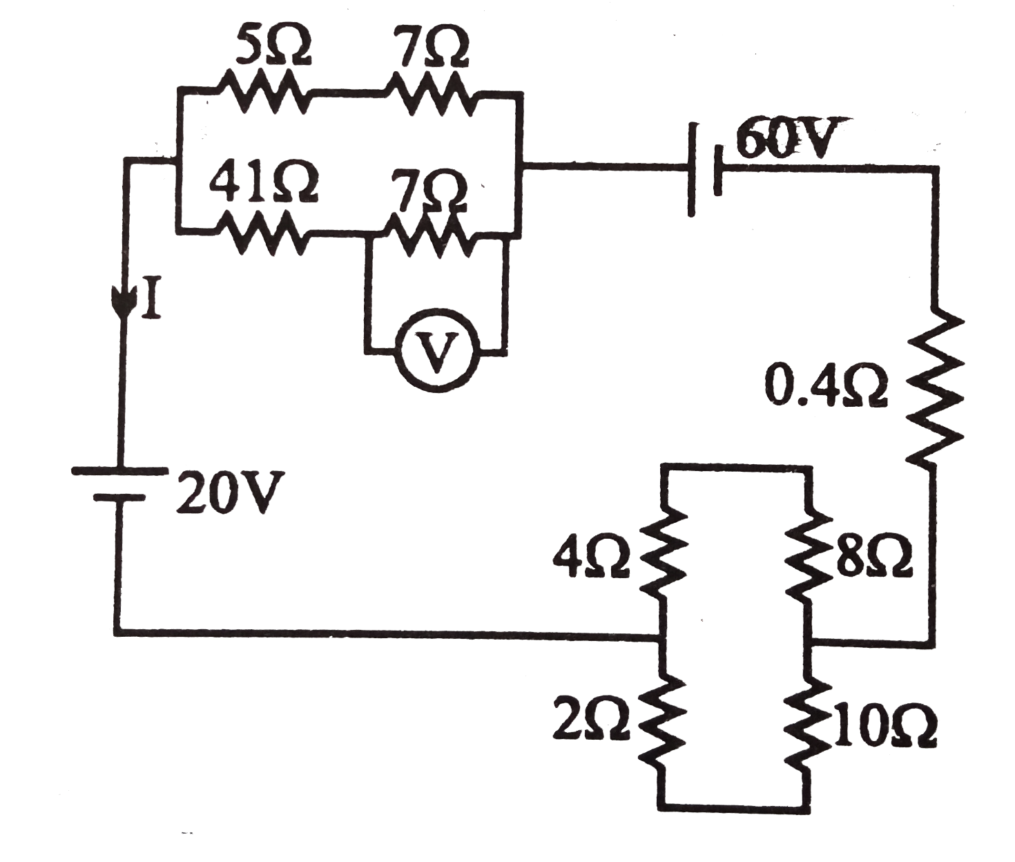 View Solution
Find the current I & voltage V in the circuit shown.
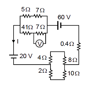 View Solution
The potential harrier for Si is ………………….V and for Ge is ………………..V
View SolutionIn the circuit shown in figure, Voltage V0 is–
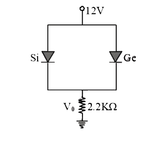 View Solution
In the circuit shown in figure, Voltage V0 is
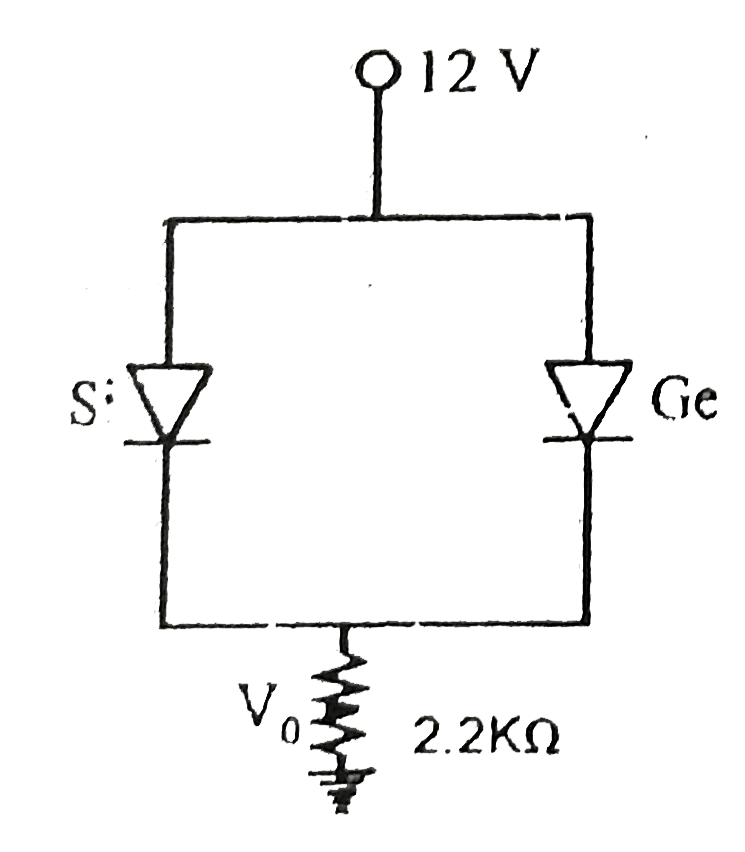 View Solution
In the circuit shown infigure, voltage V0 is,View SolutionFind the potential difference Va−Vbin the circutis shown in figure
 View Solution
In the circuit shown in figure the maximum output voltage V0 is
 View Solution
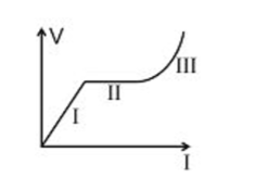
Voltage V v/s I graph is shown in the figure.
 View Solution

