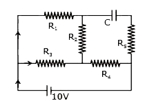
In the circuit shown, the cell is ideal , with . Ecah resistance is of the potential difference across the capacitor is
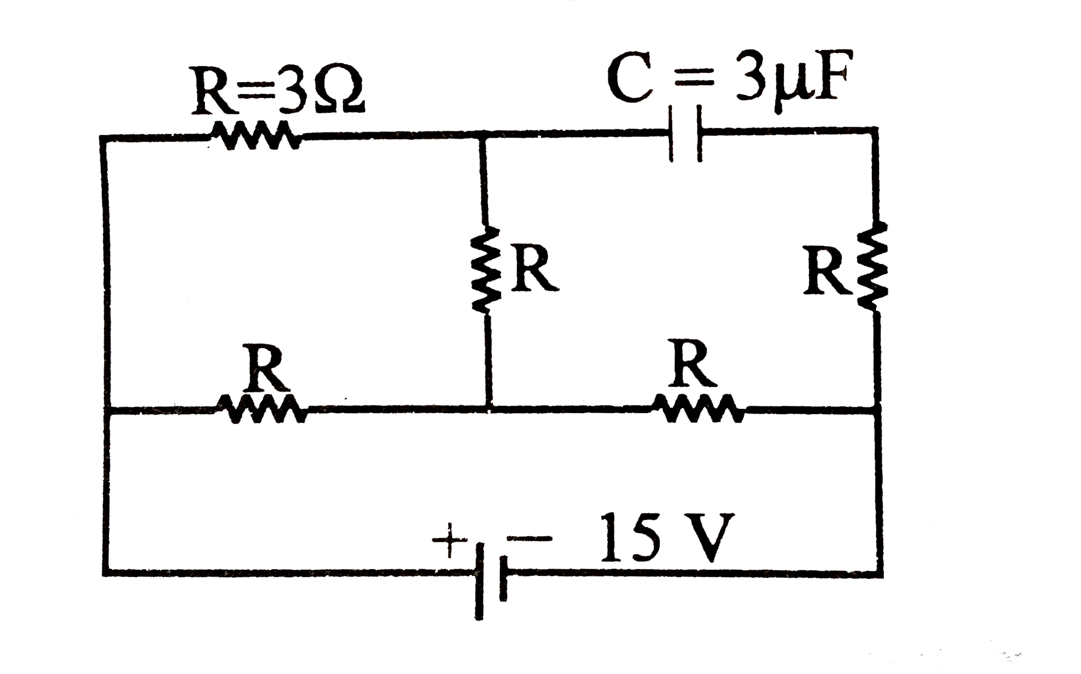
A
zero
B
C
D
Video Solution
Text Solution
The correct Answer is:C

.
|
Topper's Solved these Questions
- THERMAL AND ELECTRIC EFFECT oF CURRENTBook:CP SINGHChapter:THERMAL AND ELECTRIC EFFECT oF CURRENTExercise:Exercises
Explore 101 Videos
- SEMICONDUCTORSBook:CP SINGHChapter:SEMICONDUCTORSExercise:Exercises
Explore 140 Videos
- WAVE NATURE OF LIGHTBook:CP SINGHChapter:WAVE NATURE OF LIGHTExercise:EXERCISES
Explore 140 Videos
Similar Questions
Knowledge Check
In the circuit shown in fig. the cell is ideal with emf 15V. Each resistance is of 3Ω. The potential difference across the capacitoro in steady state is
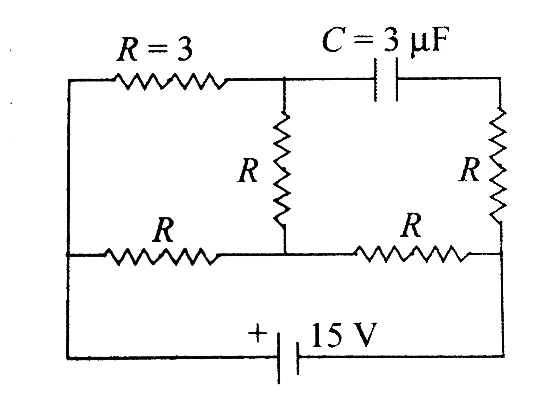 A0B9 VC12 VD15 V
In the circuit shown the cell is idea with end =15V each resistance is of 3Ω The potential difference the capacitor is
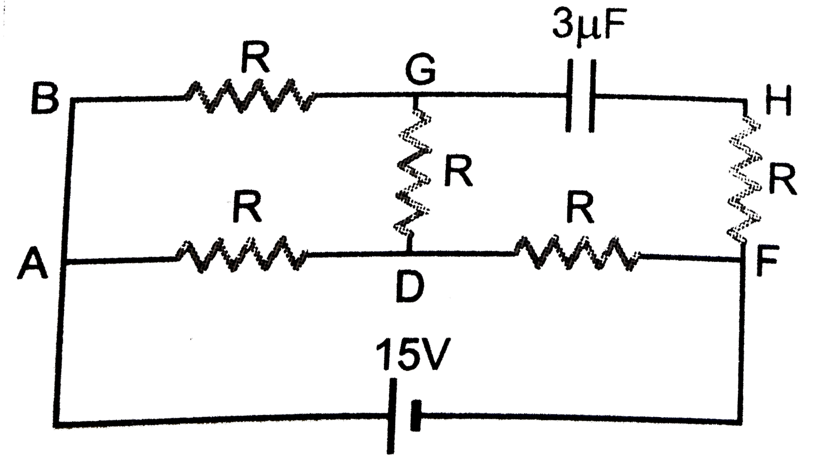 AzeroB9VC12VD15V
In the circuit shown in the figure, the potential difference across the 4.5μF capacitor is
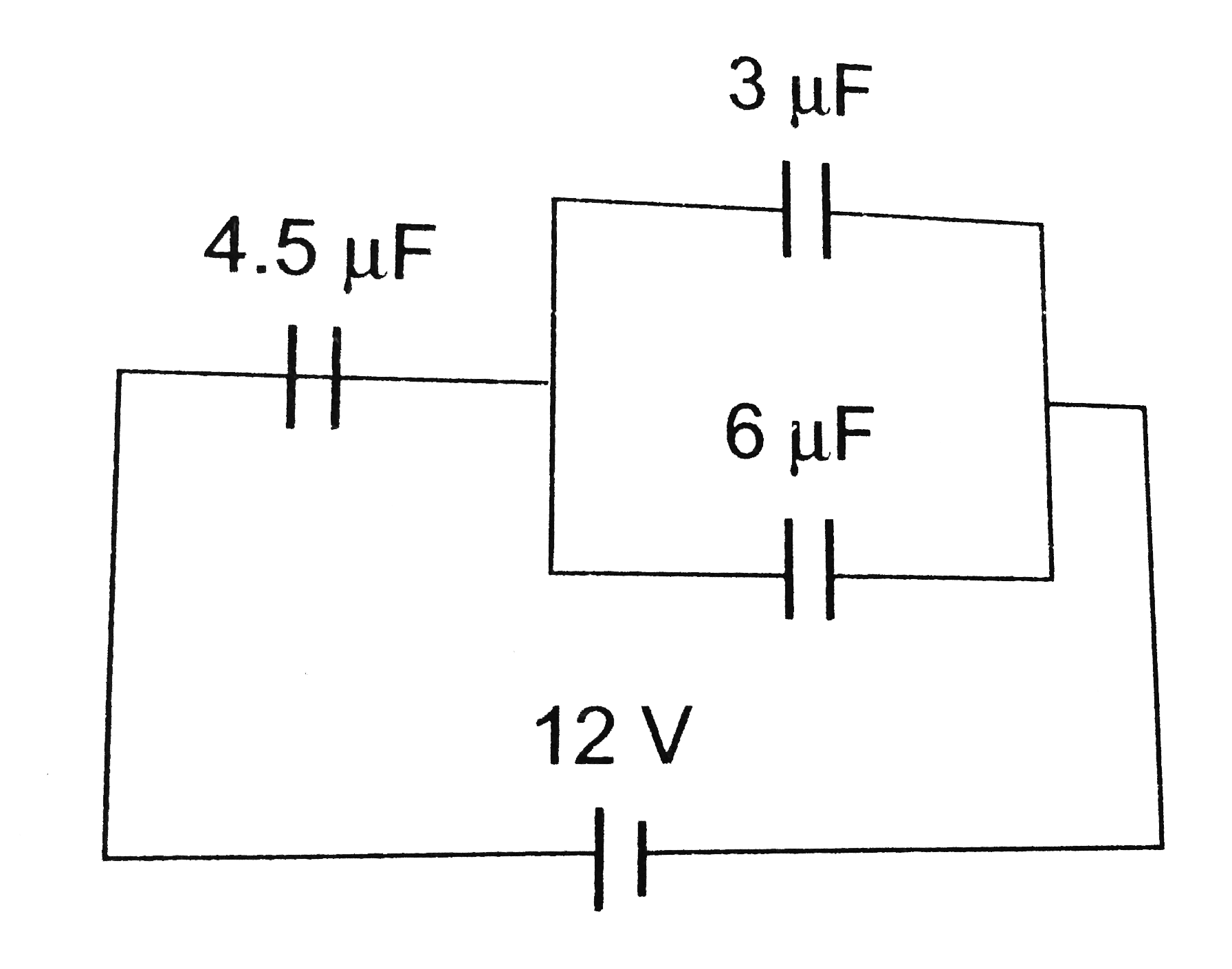 A83voltsB4 voltsC6 voltsD8 volts
What is the potential difference across 2μF capacitor in the circuit shown?
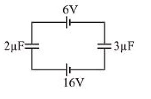
View SolutionWhat is the potential difference across 2μF capacitor in the circuit shown?
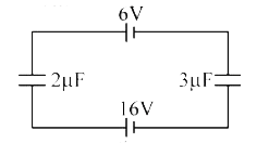
View SolutionIn the circuit shows in Fig. 6.63, the cell is ideal with emf 9V. If the resistance of the coil of galvanometer is 1Ω, then
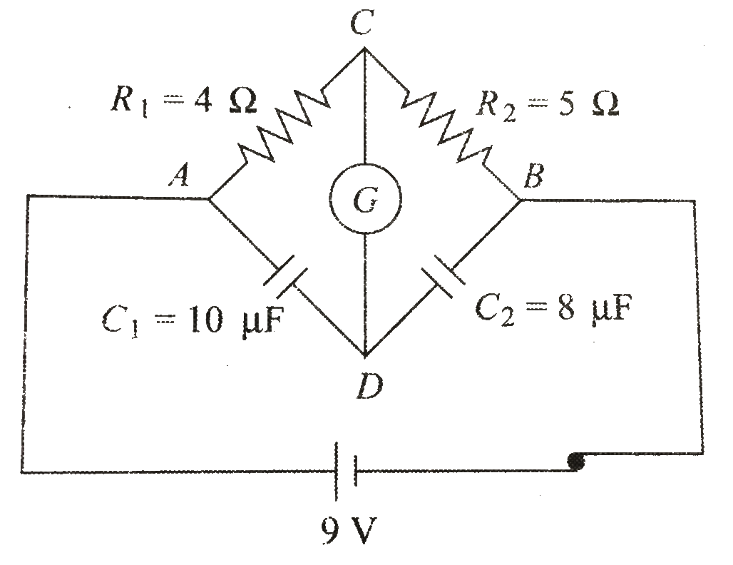
View SolutionIn the circuit shown, the cell is ideal with emf = 2V . The resistance of the coil of the galvanometer G is 1Ω.

(i) No current flows in G
(ii) 0.2A current flows in G
(iii) potential difference across C1is1V
(iv) Potential difference across C2 is 1.2V
View SolutionIn the circuit shown below:

The potential difference across the 3Ω resistor is:
View Solution


