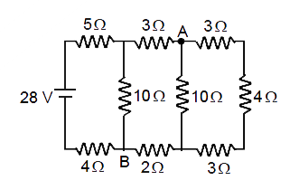
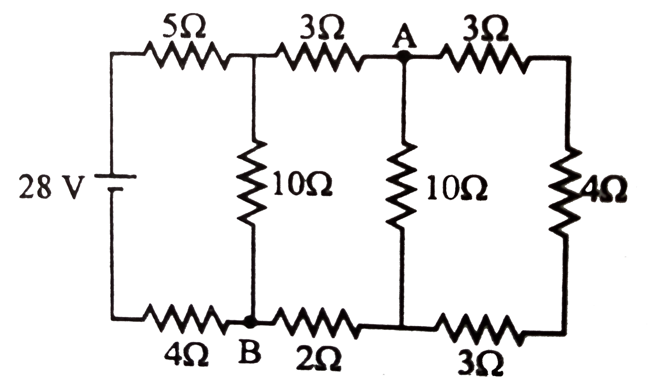
Consider the circuit shown in the figure
A
the current in the 5Ω resistor is 2A
B
the current in the 5Ωresistor is 1A
C
the potential difference VA−VB is 10V
D
the potential difference VA−VB is 5V
Video Solution
Text Solution
The correct Answer is:A
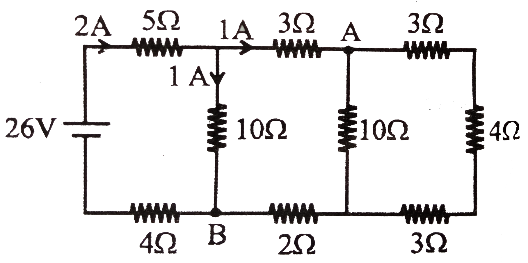
Req=14Ω
I=2814=2Amp
VA+3×1−10×1=VB
VA−VB=7 volt
|
Similar Questions
Knowledge Check
In the circuit shown in the figure
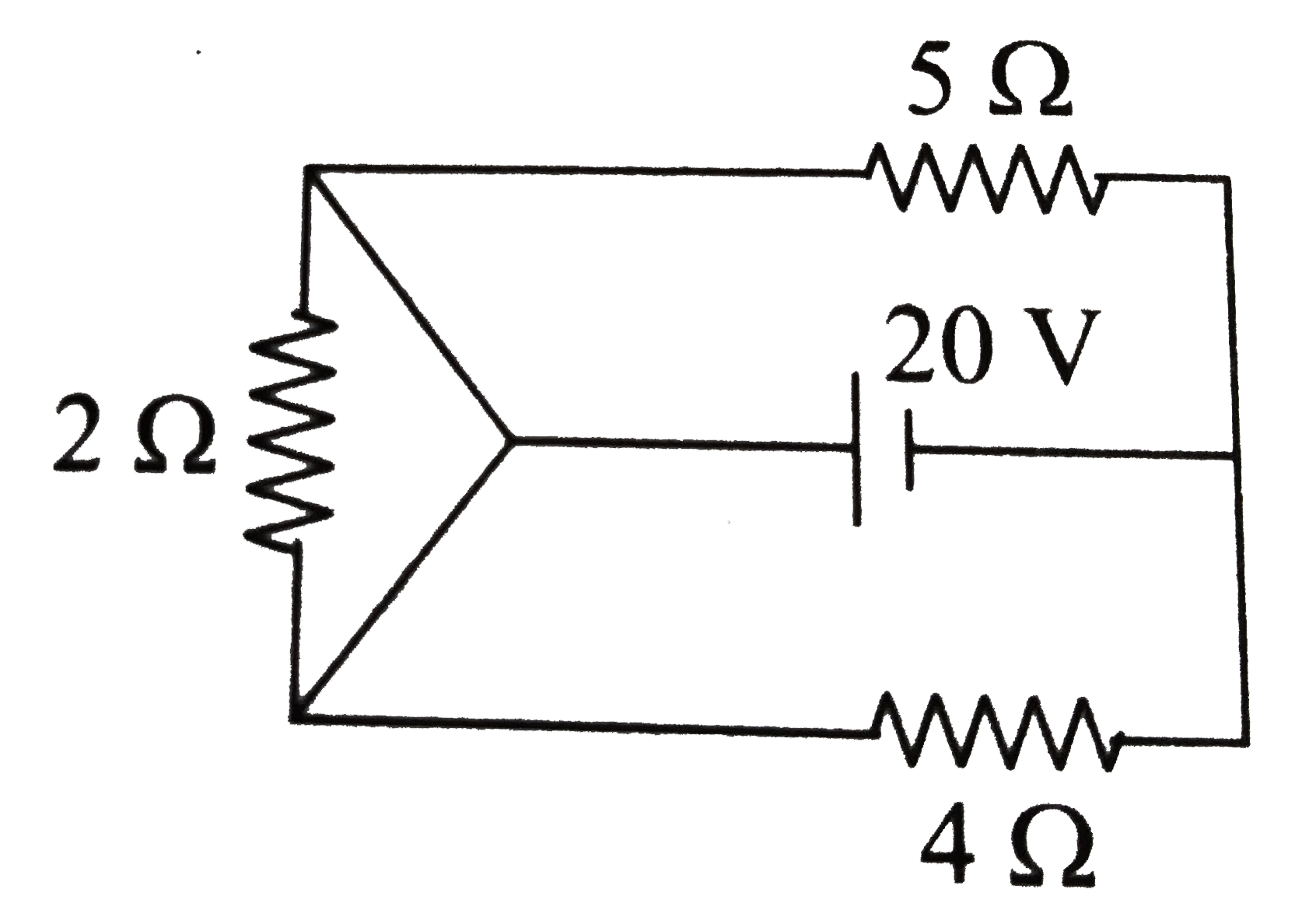 . Acurrent passing through 2Ω resistance is zero.Bcurrent passing through 4Ω resistance is 5ACcurrent passing through 5Ω resistance is 4A.Dpotential difference across 2Ω resistance is zero.
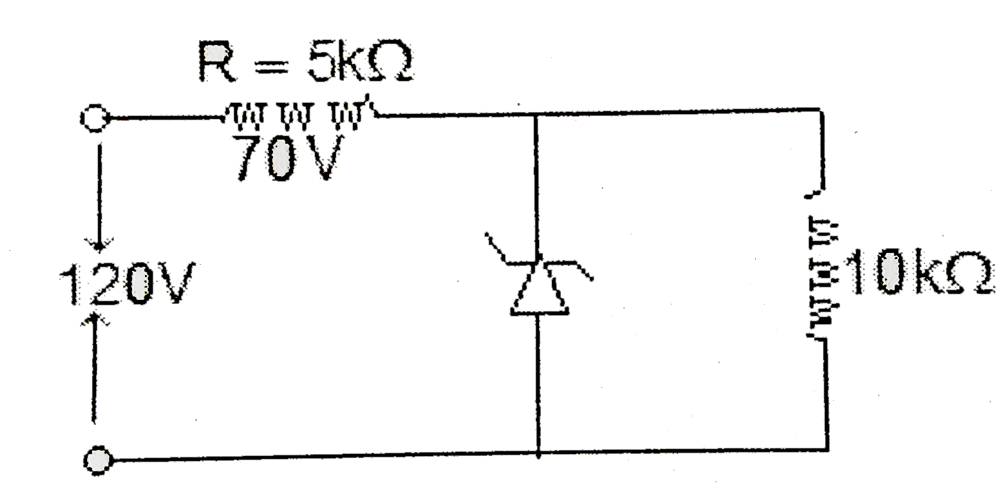
For the circuit shown in the figure:Acurrent through zener diode is 4 mA.Bcurrent through zener diode is 9 mACthe output voltage is 50 VDthe output voltage is 40 VFor the circuit shown in the figure :
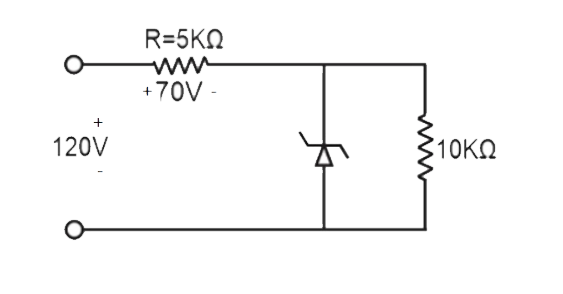 ACurrent through Zener diode is 4 mABCurrent through Zener diode is 9 mACThe output voltage is 60 VDThe output voltage is 40 V
For the circuit shown in the figure
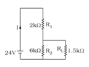
View SolutionFor the circuit shown in the figure
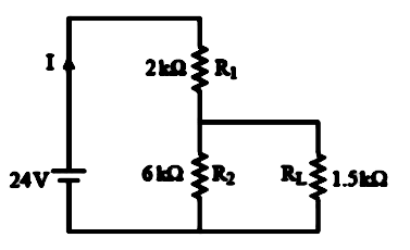
View SolutionConsider the LR circuit shown in the figure. If the switch S is closed at t = 0 then the amount of charge that passes through the battery between t=0 and t=LR is
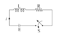
View SolutionIn the circuit shown in the figure,
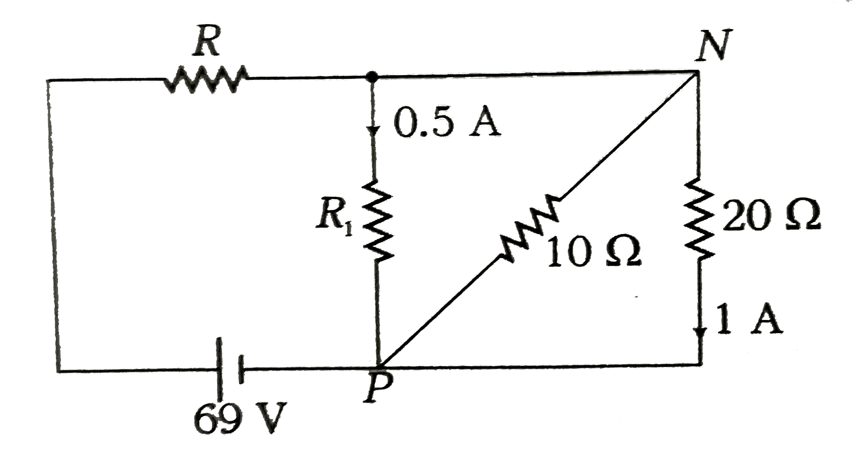
View SolutionConsider the circuit shown in figure, the current l3 is equal to
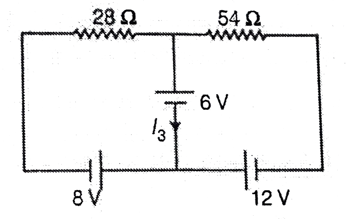
View Solution


