For the circuit shown in the figure
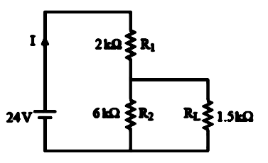
A
the potential different across RL is 18 V
B
The current I through the battery is 7.5 mA
C
Ratio of power dissipated in R1 and r2 is 3
D
If R1 and R2 are interchanged maguitude of power dissipated in rL will decrease by a factor of 9
Video Solution
|
Answer
Step by step video & image solution for For the circuit shown in the figure by Physics experts to help you in doubts & scoring excellent marks in Class 12 exams.
Updated on:21/07/2023Similar Questions
Knowledge Check
Consider the circuit shown in the figure
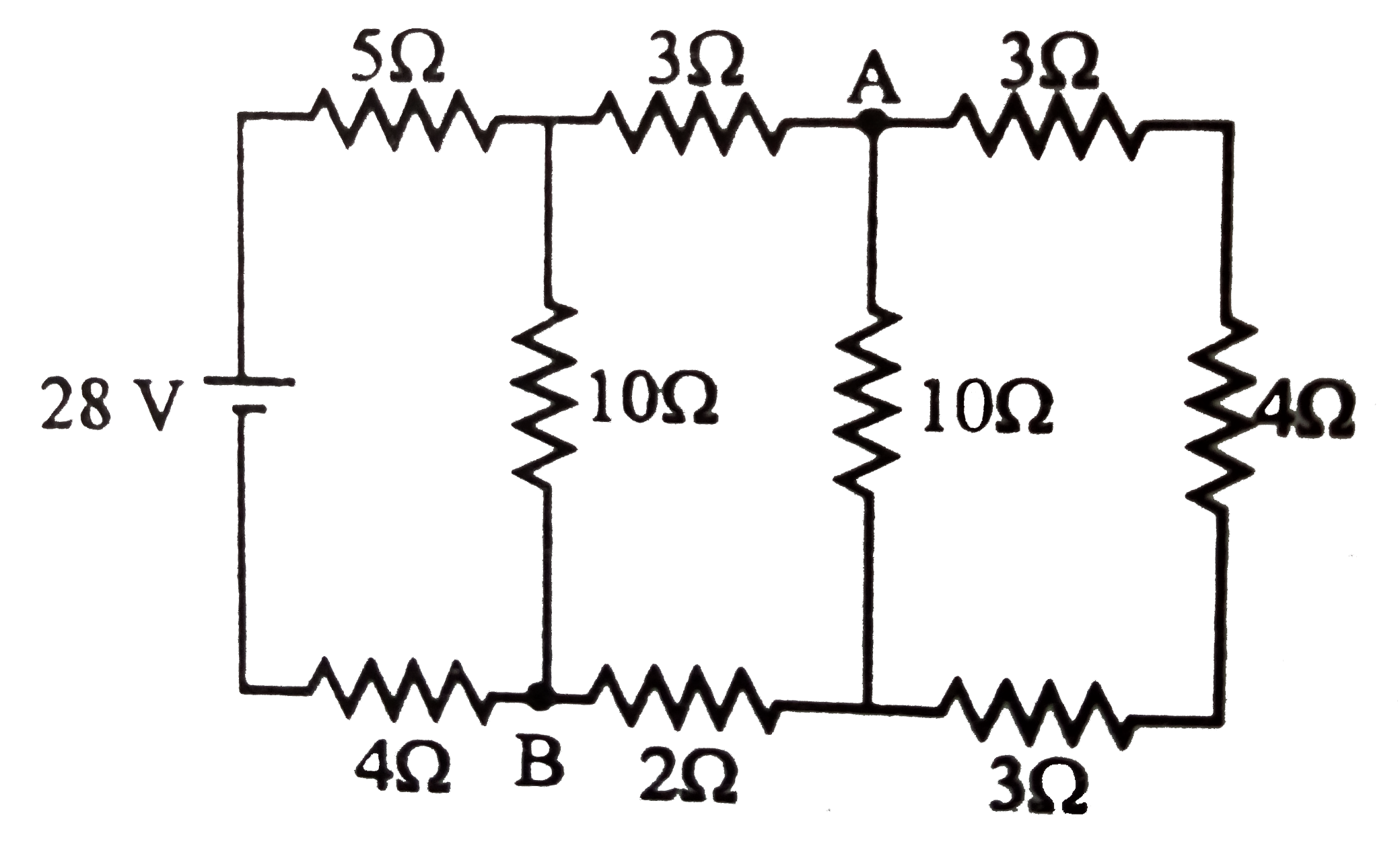 Athe current in the 5Ω resistor is 2ABthe current in the 5Ωresistor is 1ACthe potential difference VA−VB is 10VDthe potential difference VA−VB is 5V
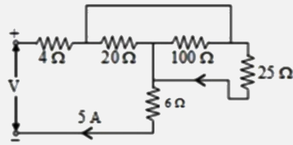
In the circuit shown in the figure
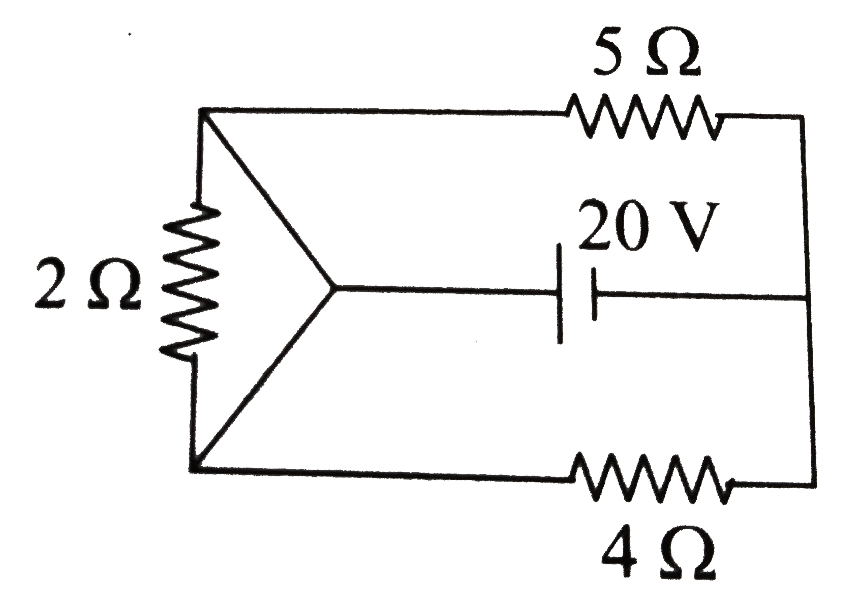 . Acurrent passing through 2Ω resistance is zero.Bcurrent passing through 4Ω resistance is 5ACcurrent passing through 5Ω resistance is 4A.Dpotential difference across 2Ω resistance is zero.
The power factor of the circuit shown in the figure is
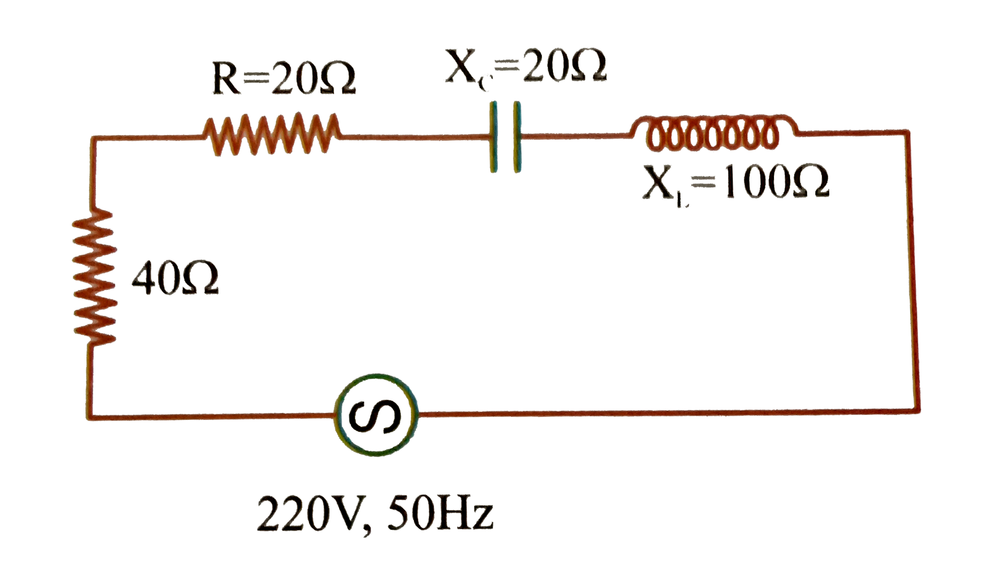 A0.4B0.2C0.8D0.6
In the circuit shown in the figure , V must be -
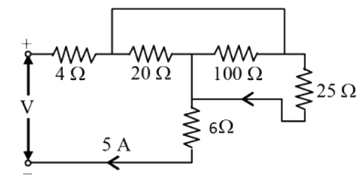
View SolutionThe natural frequency of the circuit shown in the figure is
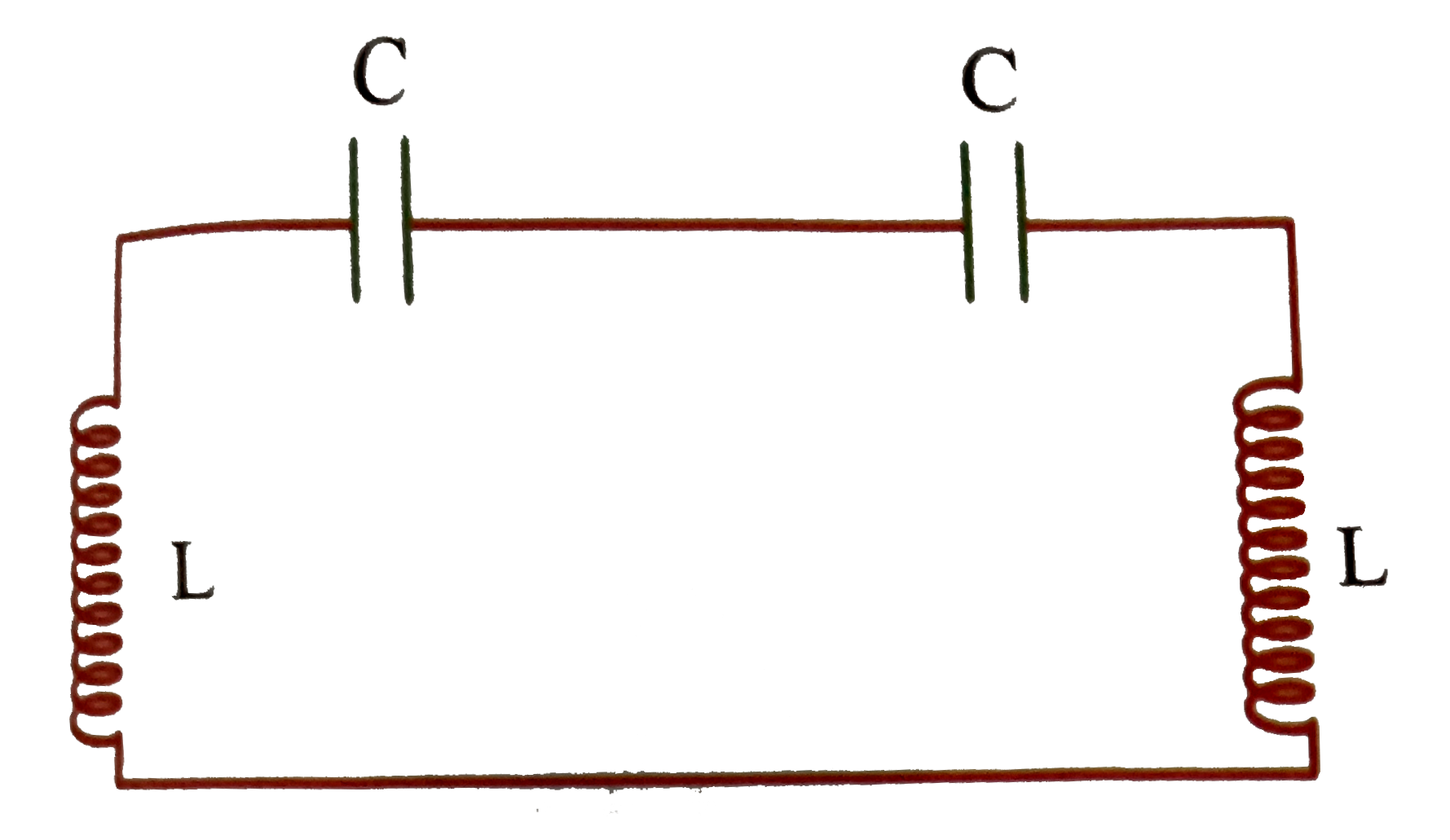
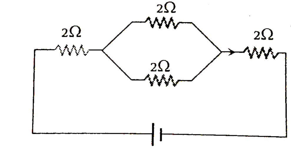
View SolutionThe equivalent resistance of the circuit shown in the figure is
View SolutionThe time constant of the circuit shown in the figure is
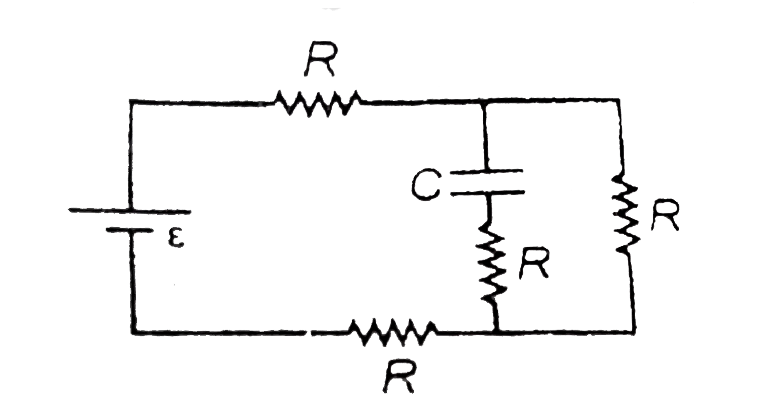
View SolutionThe time constant of the circuit shown in the figure is
View Solution


