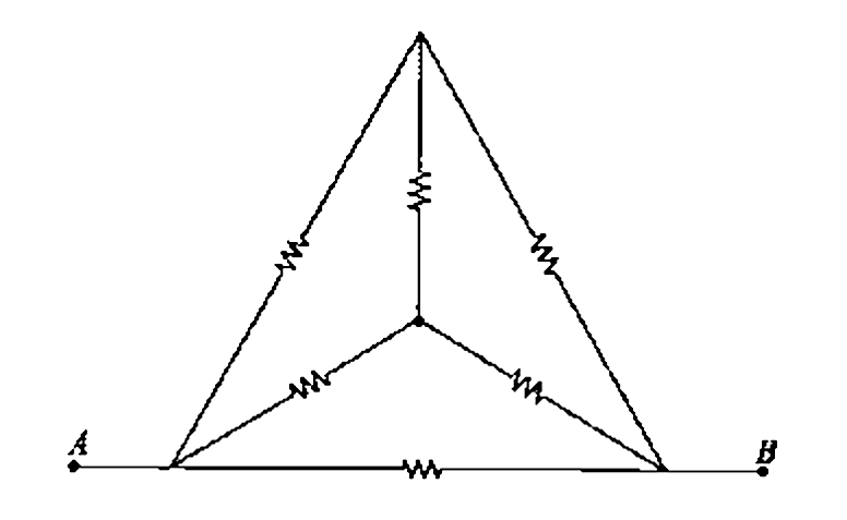
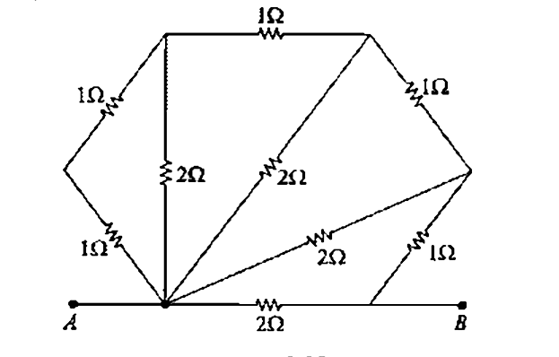
The equivalent resistance of the circuit shown in the figure is
A
8Ω
B
6Ω
C
5Ω
D
4Ω
Video Solution
Text Solution
The correct Answer is:C
|
Answer
Step by step video, text & image solution for The equivalent resistance of the circuit shown in the figure is by Physics experts to help you in doubts & scoring excellent marks in Class 12 exams.
Updated on:21/07/2023Topper's Solved these Questions
- CURRENT ELECTRICITYBook:ERRORLESS Chapter:CURRENT ELECTRICITYExercise:Kirchhoff s Law, cells
Explore 8 Videos
- CURRENT ELECTRICITYBook:ERRORLESS Chapter:CURRENT ELECTRICITYExercise:Different Measuring Instruments
Explore 1 Video
- COMMUNICATION SYSTEMBook:ERRORLESS Chapter:COMMUNICATION SYSTEMExercise:S E T
Explore 14 Videos
- ELECTRO MAGNETIC INDUCTIONBook:ERRORLESS Chapter:ELECTRO MAGNETIC INDUCTIONExercise:SET
Explore 20 Videos
Similar Questions
Knowledge Check
The equivalent resistance of the circuit shown in figure between the points A and B if VA<VB is
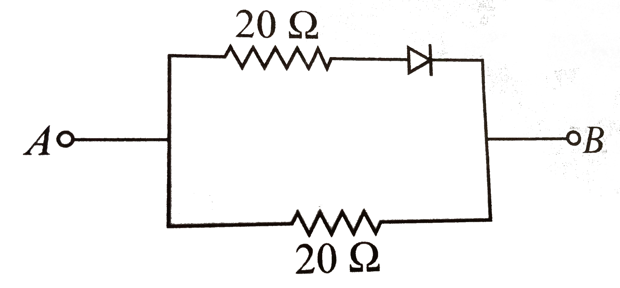 A10ΩB20ΩC5ΩD40Ω
The equivalent capacitance in the circuit shown in figure will be
 A103μFB4μFC6μFD8μF
The equivalent capacitance CAB of the circuit shown in the figure is.
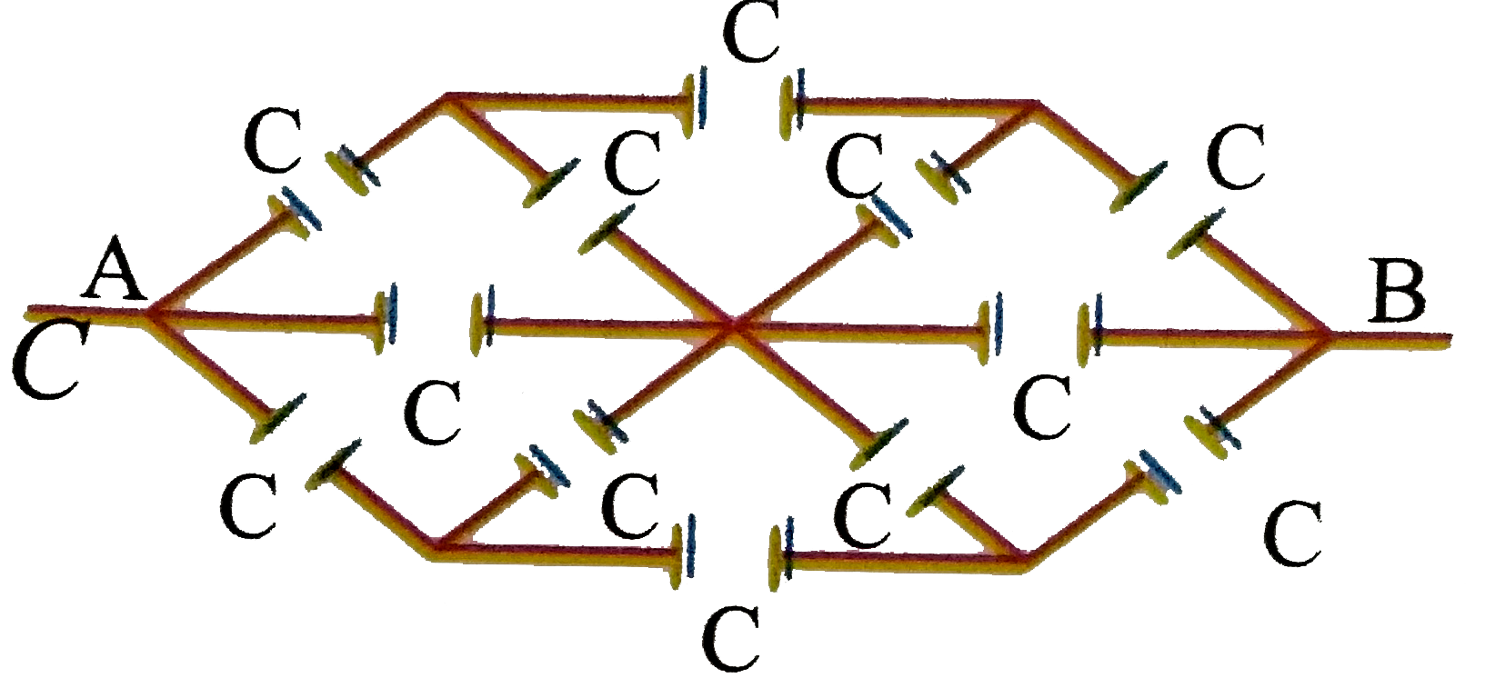 .A54CB45CC2 CDC
Find the equivalent resistance of the circuit shown in figure between the points a and b.Each resistor has a resistances r.
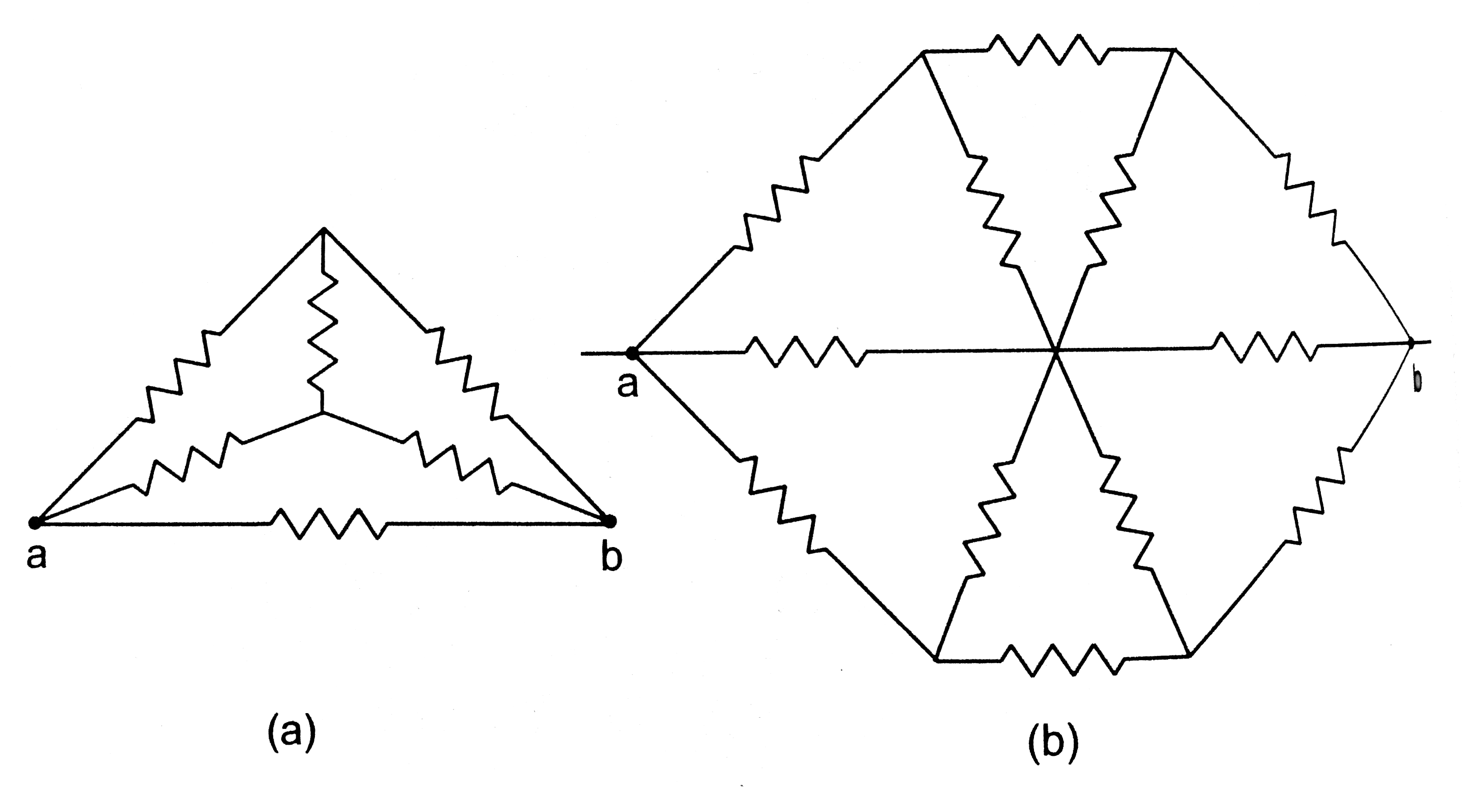
View SolutionFind the equivalent resistance of the circuits shown in figure between the points a and b. Each resistor has a resistance r.
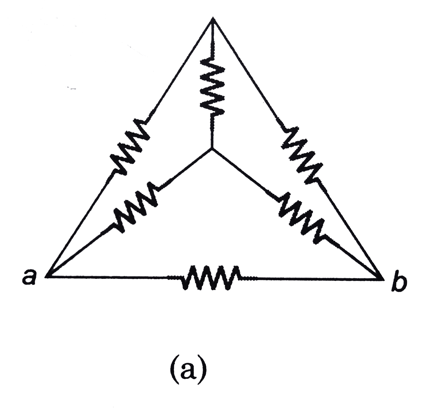
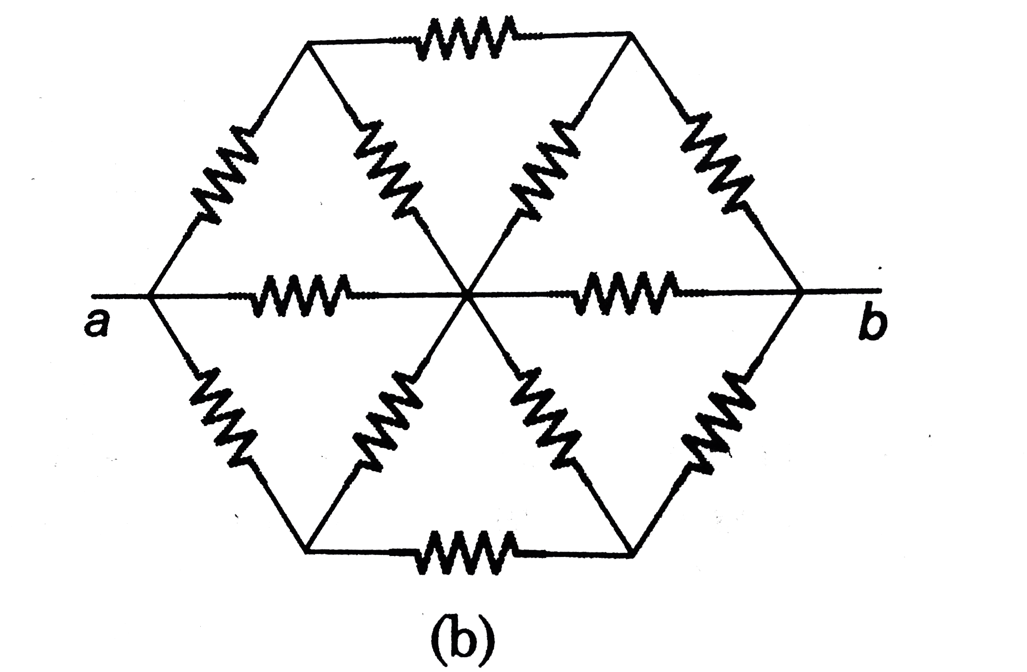
View SolutionFind equivalent resistance of the circuit shown in figure 3.32 across terminals A and B.
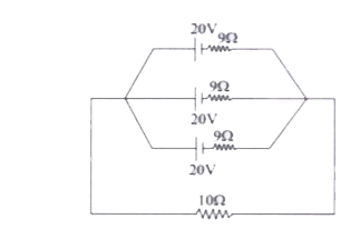
View SolutionWhat is equivalent resistance on the circuit shown in the given circuit ?
View Solution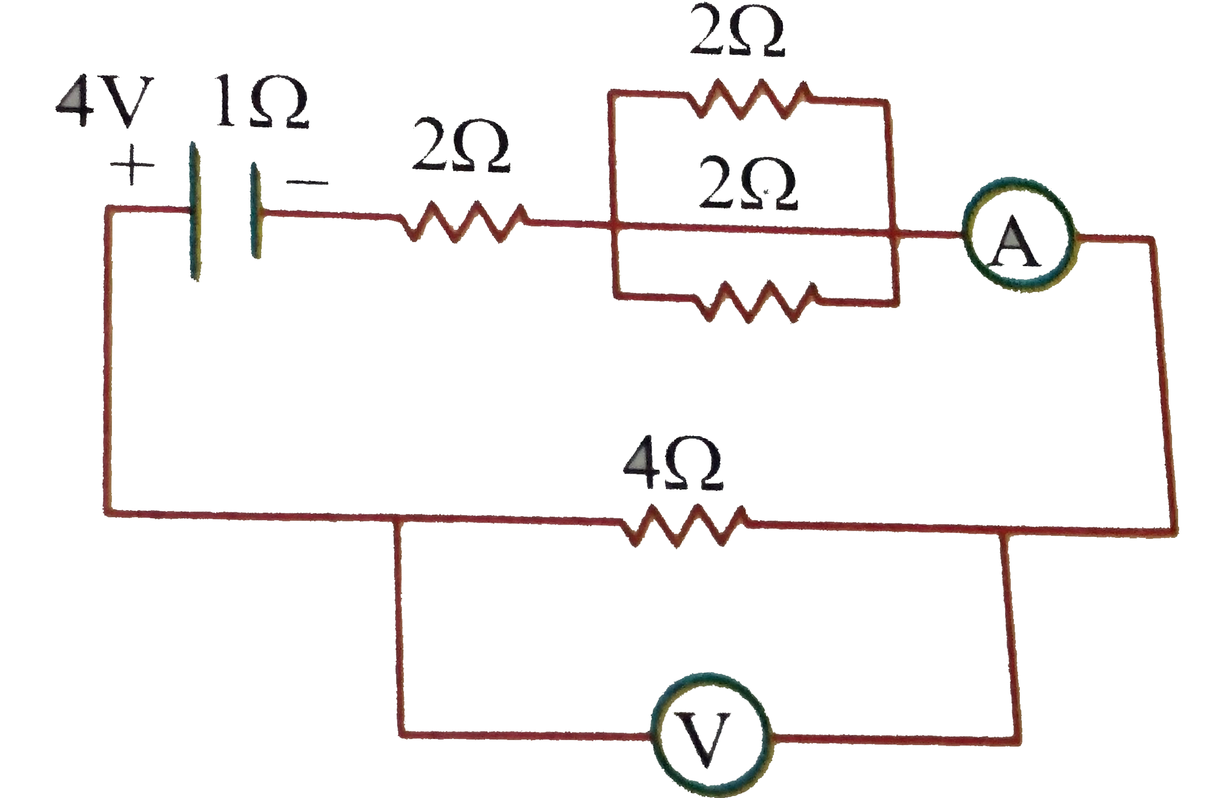
What is the equivalent resistance of the circuit
View Solution


