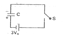
In the circuit shown in the figure the total enegry of is dissipated in the resistor when the switch is cloed. The initially charge on the capacitor is
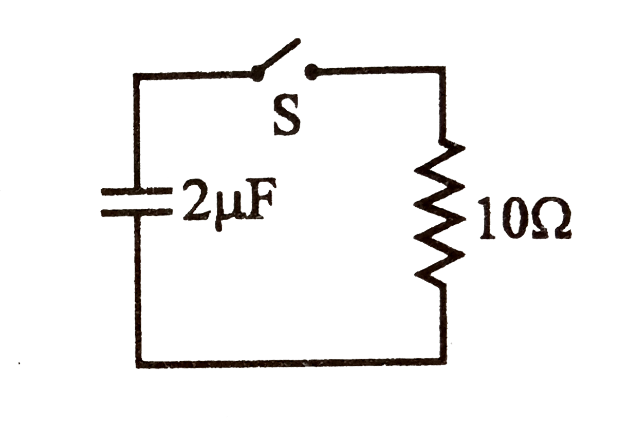
The correct Answer is:B
Similar Questions
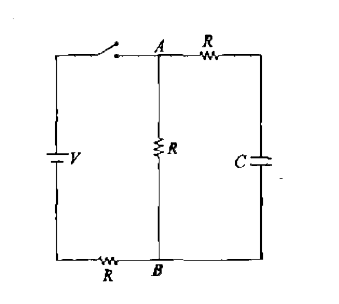
In the circuit shown in figure-3.244, the battery is an ideal one with emf V. The capacitor is initially uncharged. The switch S is closed at time t=0.
(a) Find the charge Q on the capacitor at time l
(b) Find the current in branch AB at time just after closing the switch.
 View Solution
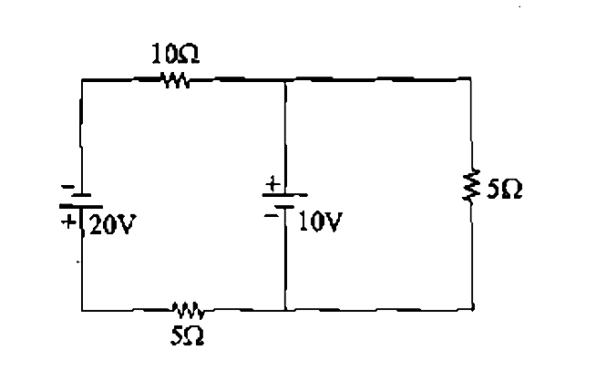
In the circuit shown in figure-3.392, find the power supplied by 10 V battery and thermal power dissipated in 10Ω resistance.
 View Solution
Knowledge Check
- Question 1 - Select One
In the circuit shown in the figure, the capacitor C is charged to a potential Vo. The heat generated in the circuit when the switch S is closed, is
ACV20B2CV20C4CV20D8CV20 - Question 2 - Select One
In the circuit shown in figure-3.348 when the switch is closed, the initial current through the 1Ω resistor just after closing the switch is
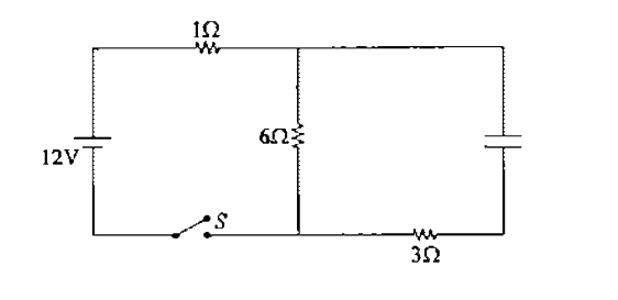 A2AB4AC3AD6A
 - Question 3 - Select One
In the circuit shown in figure, charge on 10μF capacitor is given as
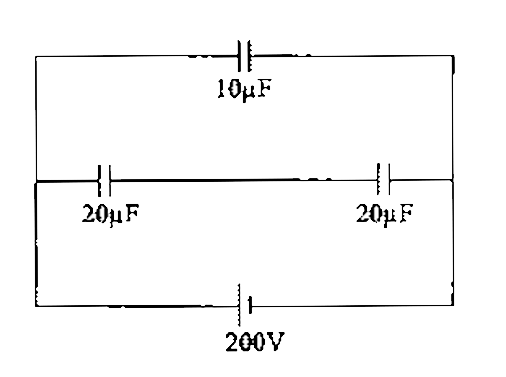 A2×10−3CB16×10−4CC4×10−3CD8×10−4C
Consider the circuit shown in figure. Find the current through the 10Ω resistor when the switch S is (a) opened (b) closed.
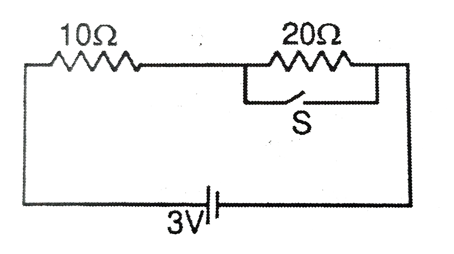 View Solution
In a part of circuit shown in the figure, the rate of heat dissipation in 4Oemga resistor is 100Js−1. Calculate the heat dissipated in the 3Ω resistor in 10 second.
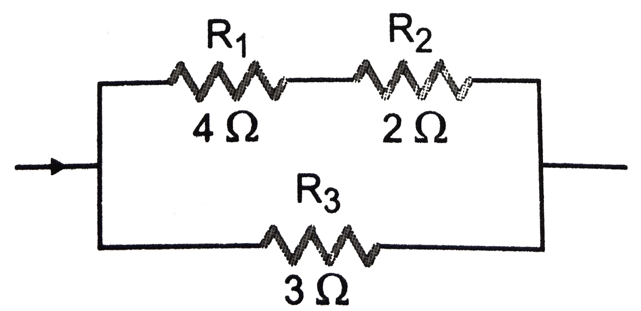 View Solution
In the circuit shown in figure 3.242 capacitor is charged with 50μC charge. Find the current in 4Ω resistance just after switch S is closed.
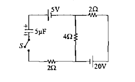 View Solution
n the circuit shown in the figure, the capacitor C is charged to a potential Vo The heat generated and charge flow, in the circuit to when the switch S is closed, is
 View Solution
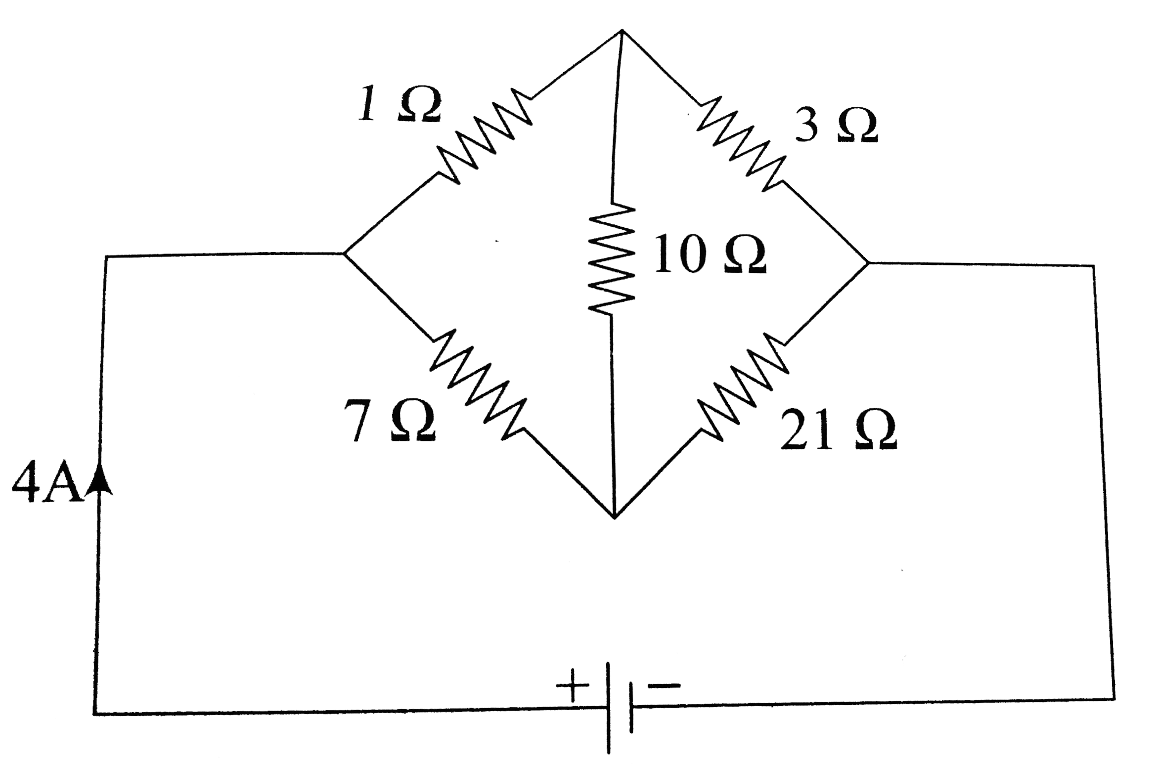
In the circuit shown in the figure, the current drawn from the battery is 4A. If 10Ω resistor is replaced by 20Ω resistor, then current drawn from the circuit will be
 View Solution

