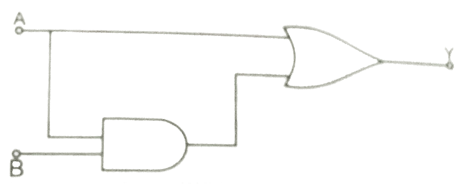
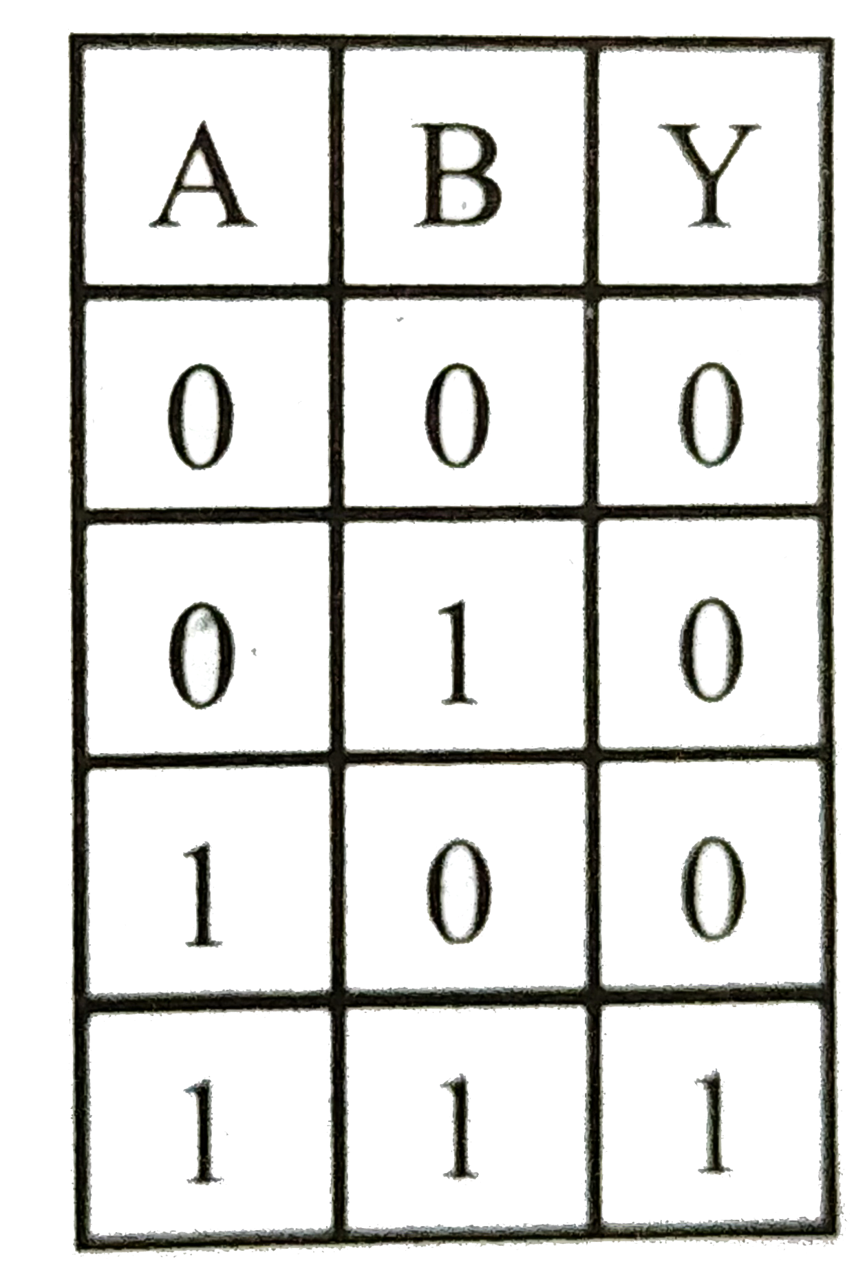
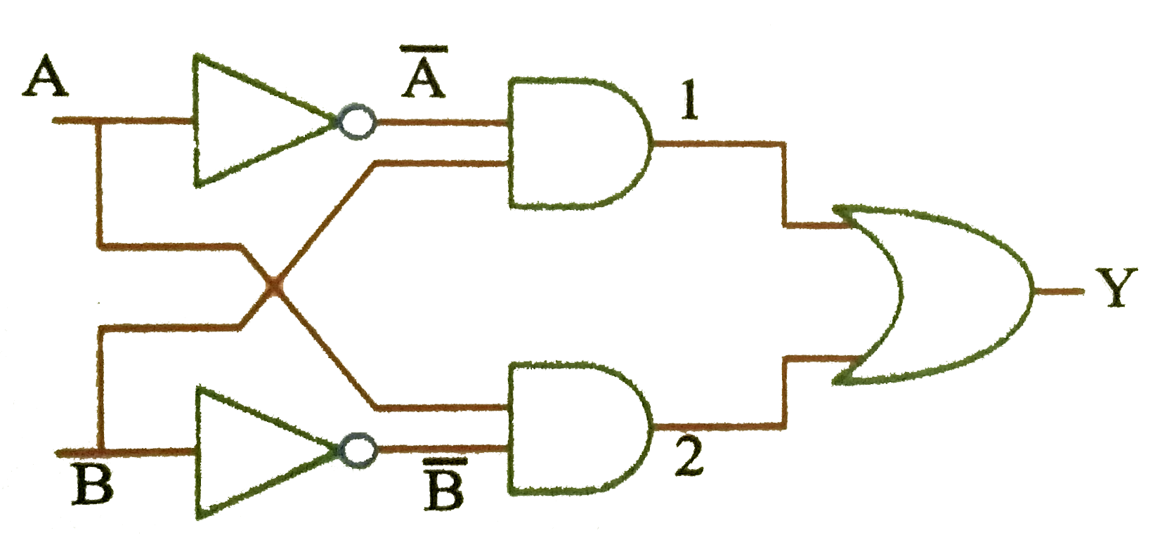
In the following circuit, the output Y for all possible inputs A and B is expressed by the truth table:

A
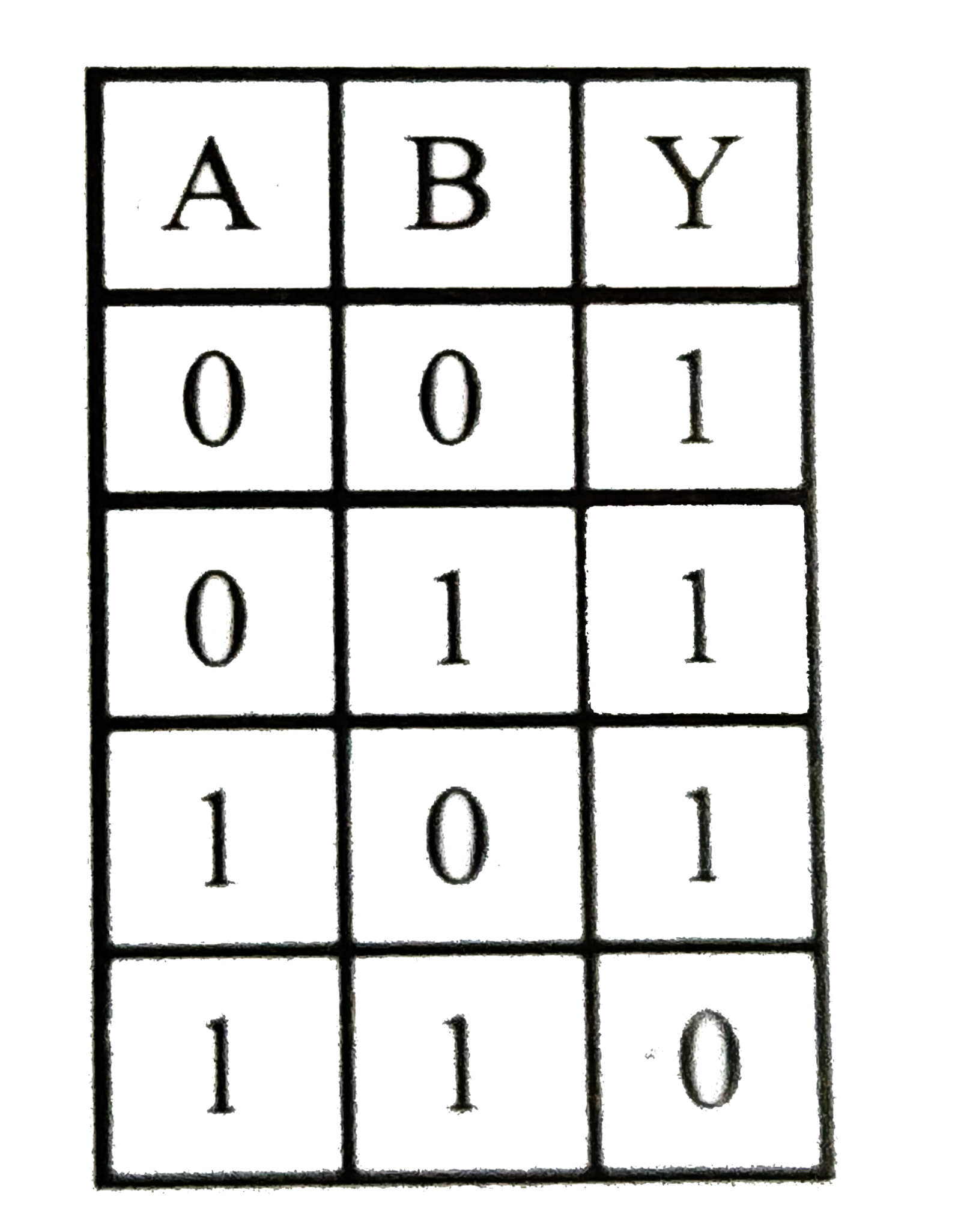
B
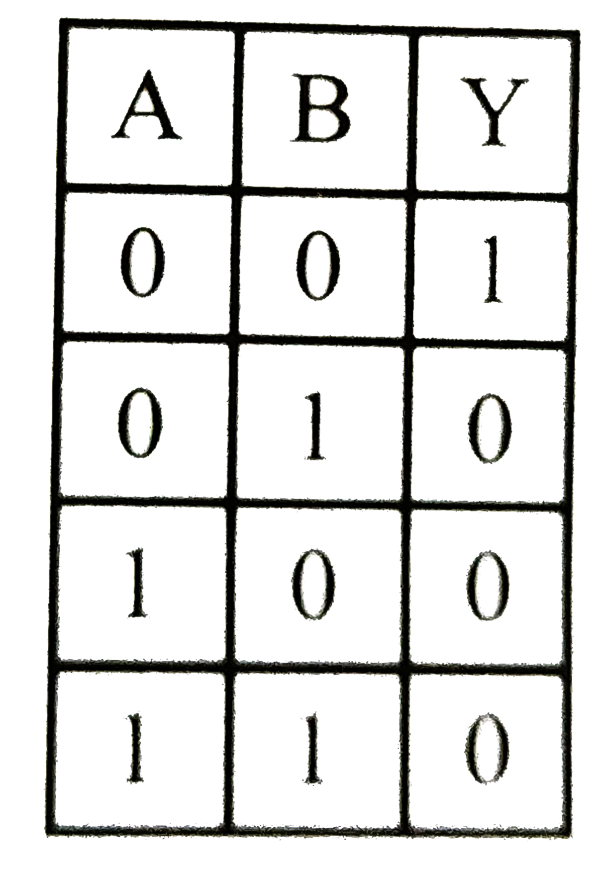
C
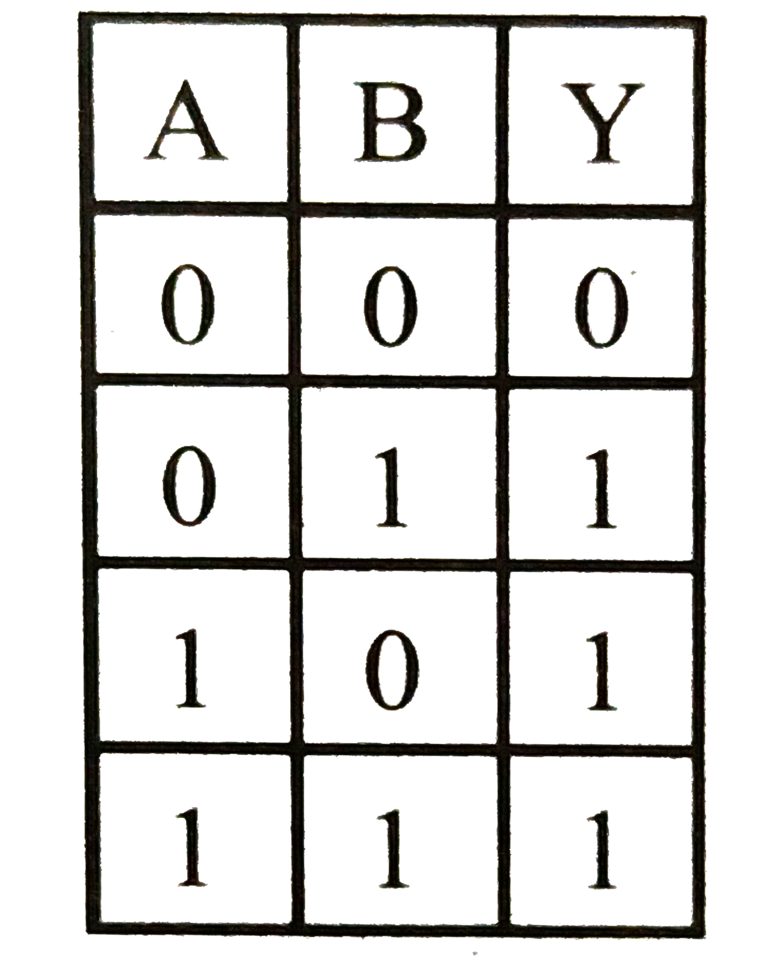
D
Video Solution
Text Solution
The correct Answer is:C

Here both (1) and (2) are NOR gates.
For gate I, output = ¯¯¯¯¯¯¯¯¯¯¯A+B
This acts as input for gate (2) .
The final output is Y=¯¯¯¯¯¯¯¯¯¯¯¯¯¯¯¯¯¯¯¯¯¯A+B=A+B
This is the Boolean expression of OR gate.
Thus the circuit acts as an OR gate and its truth table is 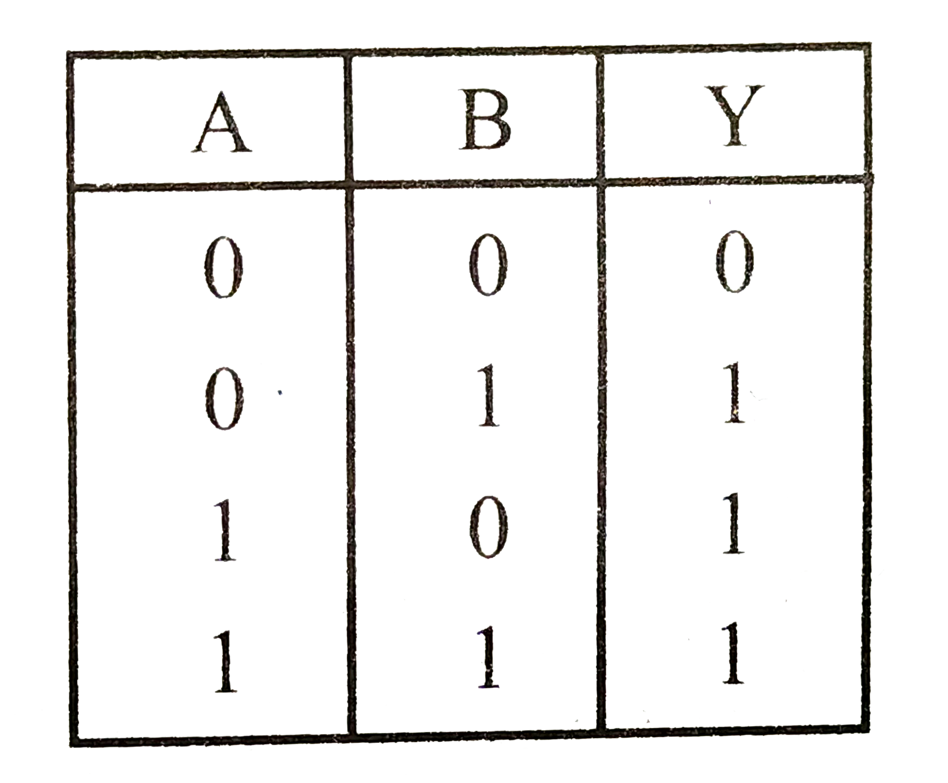
This is given in (c )
|
Topper's Solved these Questions
Similar Questions
Knowledge Check
In the following circuit the output Y becomes zero for the inputs
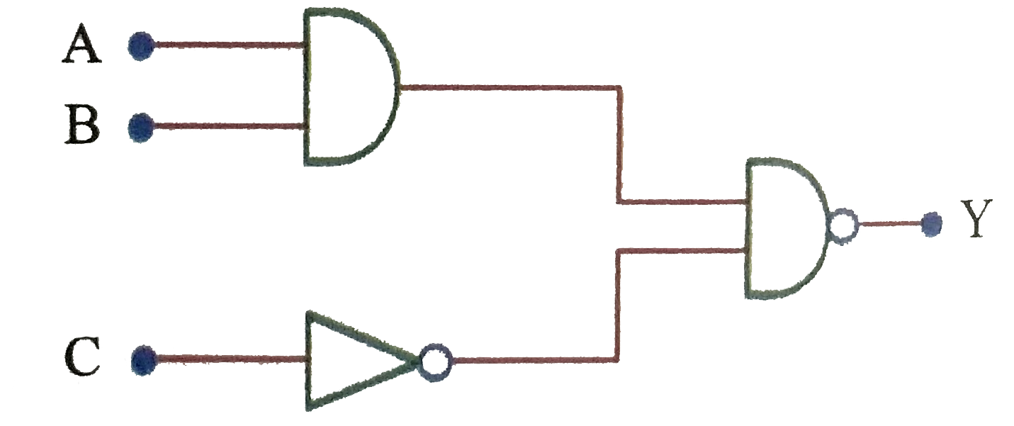 .AA=1,B=0,C=0BA=0,B=1,C=1CA=0,B=0,C=0DA=1,B=1,C=0
In AND gate, the output Y is 1 when the inputs A and B are:
AA=1, B=0BA=1, B=1CA=0, B=0DA=0, B=1In the circuit Fig. the output y becomes zero for the inputs
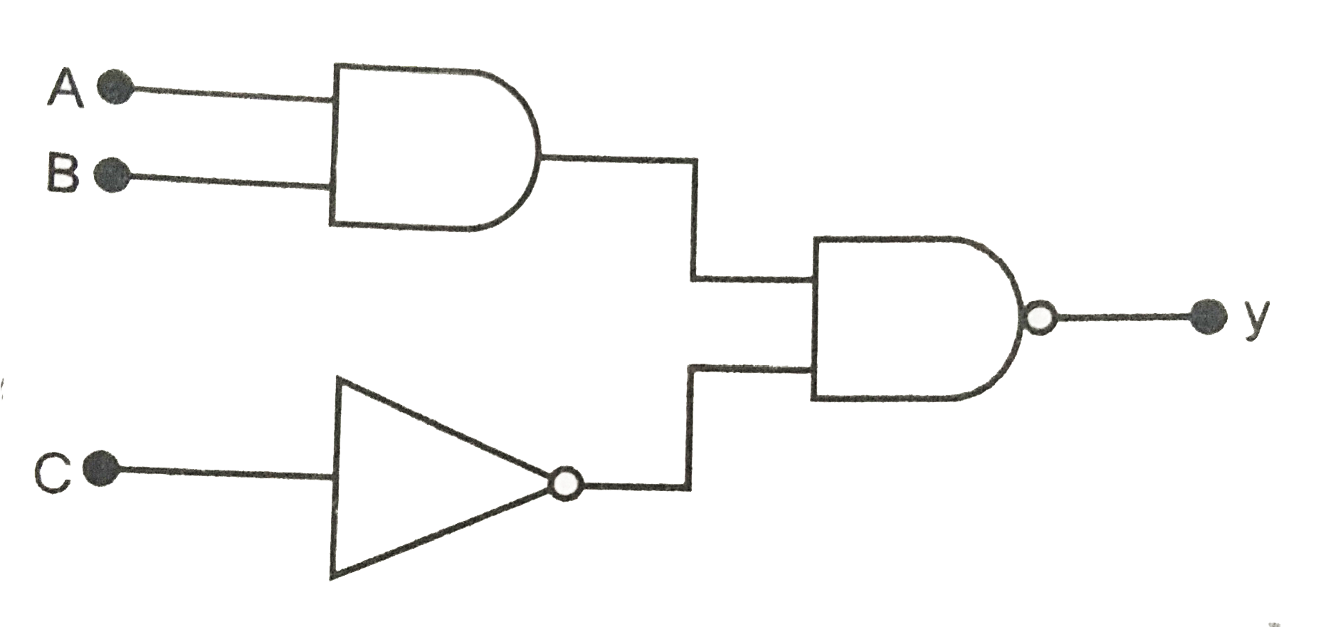 AA=1,B=0,C=0BA=0,B=1,C=1CA=0,B=0,C=0DA=1,B=1,C=0
The Boolean expression of the output Y of the inputs A and B for the circuit shown in the fig.
 .
.
View SolutionIn the logic circuit shown in the figure, if input A and B are 0 to 1 respectively, the output at Y would be ‘x’
The value of x is _______

View SolutionWhich of the following is the truth table for the circuit below ?

View SolutionThe Boolean expression of the output Y of the inputs A and B for the circuit shown in the fig.
 .
.
View SolutionIf the Output of two NAND gates is given to input of a NAND gate. Then the truth table will be of
View Solution


