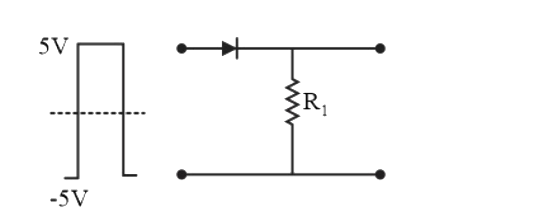
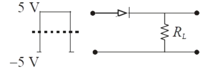
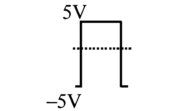
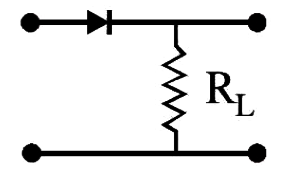
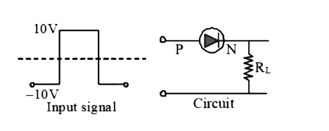
If a junction diode, a square input signal of is applied as shown.
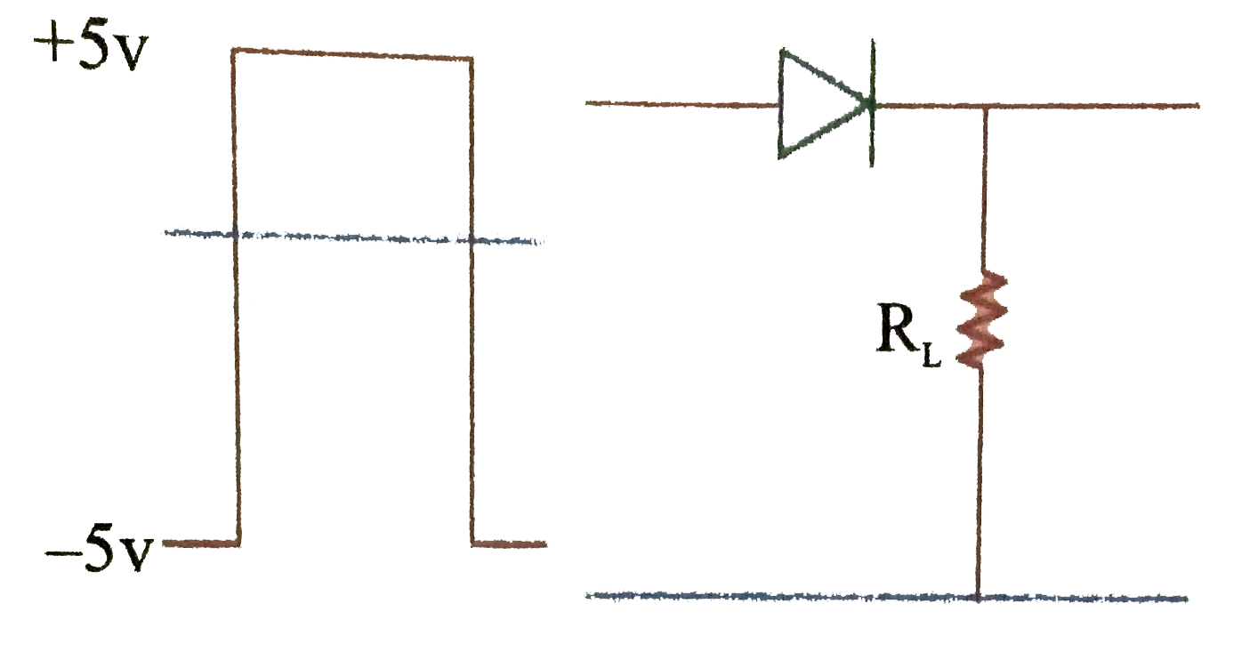
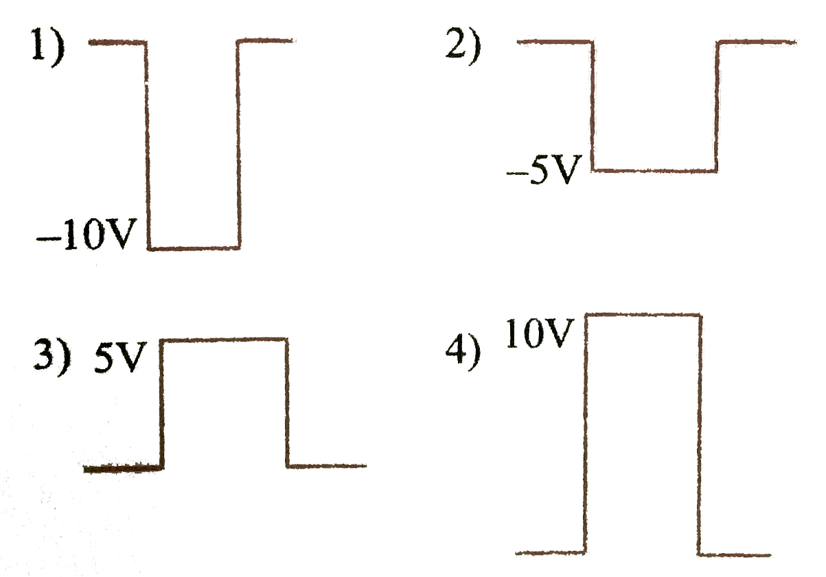
Then the out put signal across will be
 .
.
A
Figure (4)
B
Figure (3)
C
Figure (2)
D
Figure (1)
Video Solution
Text Solution
The correct Answer is:C
This is a half wave rectifier. The current will flow when it is forward biased in the first half and when V = +5V. No current will flow in the second half, when V = -5V as the diode is reverse biased.
The output across will be +5V as shown in figure (2).
|
Topper's Solved these Questions
Similar Questions
Knowledge Check
If in a p−n junction diode , a squire input single of 10V is applied as shown
 A
A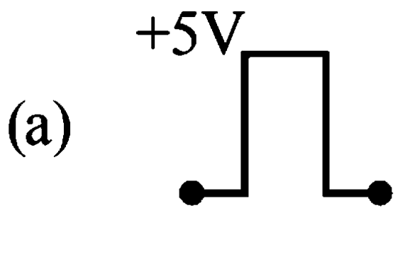 B
B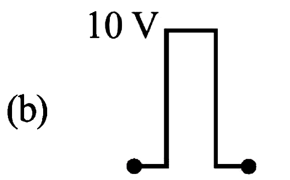 C
C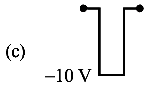 D
D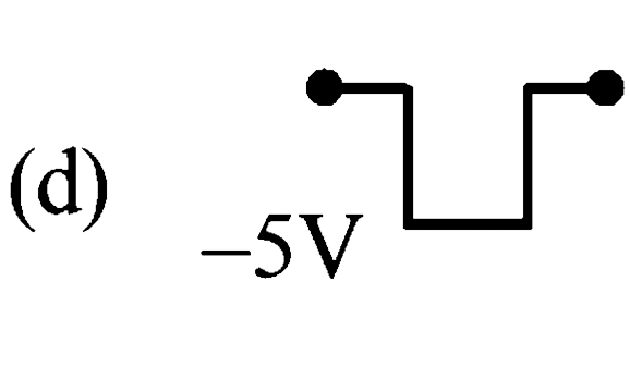
If a pn junction dide, a square input signal of 10 V is applied as shown

then the outuput signal across R1 will beA B
B C
C D
D

In p-n junction diode a square input signal of 10 V is applied as shown in figure The output signal across RL will beA B
B C
C D
D
Draw the output signal in a p-n junction diode when a square input signal of 10 v as is applied across it

View SolutionIf the following input signal is sent through a P-N junction diode, then the output signal across RL will be -
View Solution
In p-n junction diode a square input signal of 10 V is applied as shown in figure The output signal across RL will be
View SolutionIf in a p−n junction diode , a square input single of 10V is applied as shown


View SolutionIf an a p−njunction, a square input signal of 10V is applied, as shown

then the output across RL will be
View Solution


