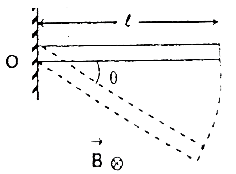
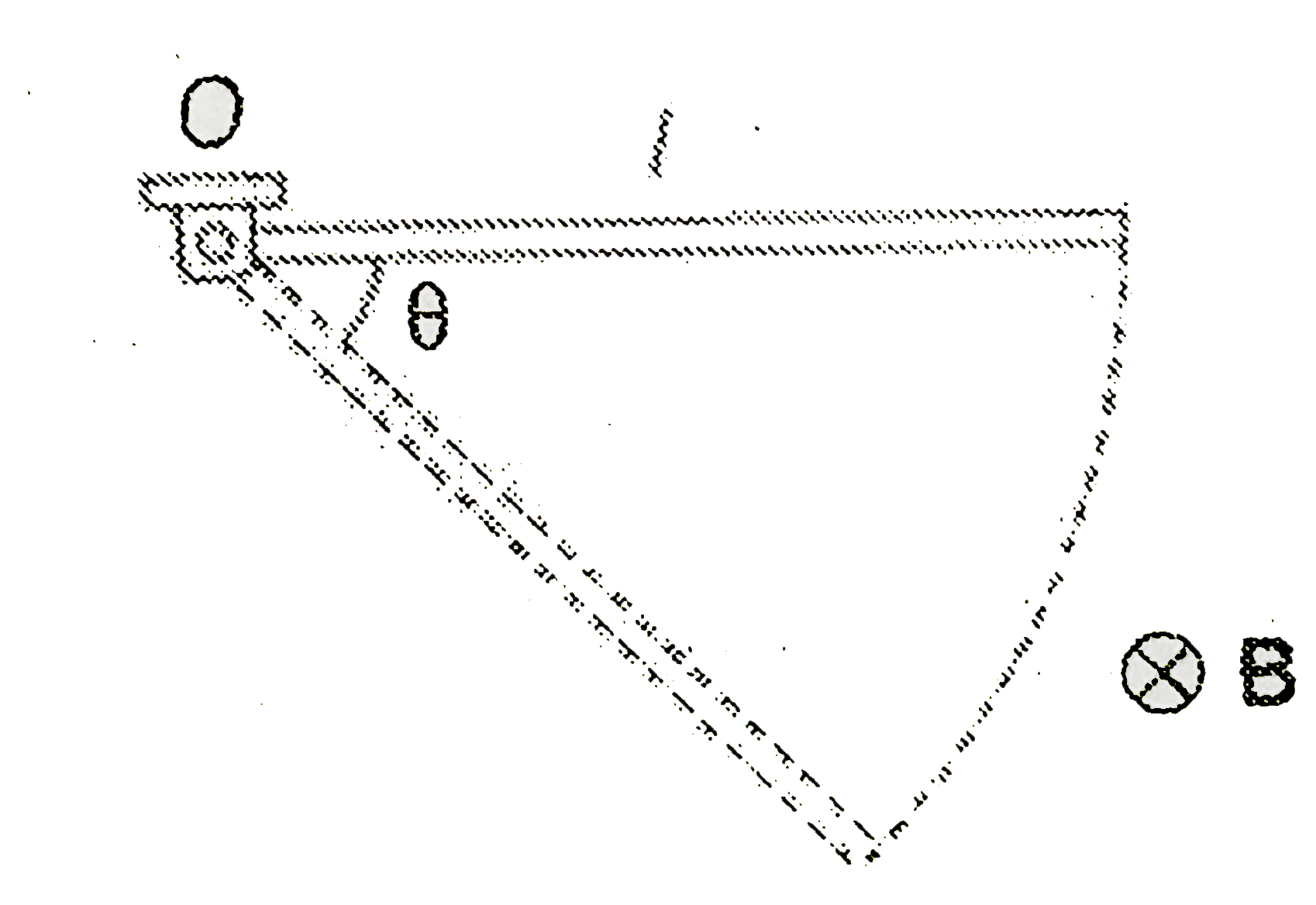
A conducting rod of length l is hinged at point O. It is free to rotate in vertical plane. There exists a uniform magnetic field →B in horizontal direction. The rod is released from position shown in the figure. Potential difference between two ends of the rod is proportional to

(a) l3/2
(b) l2
(c ) sinθ
(d) (sinθ)1/2
The correct Answer is:B, D
(b, d): Potential difference =12Bωl2
From energy conservation: mg=l2sinθ=12Iω2, where I=ml23
→ ω∝(sinθ)1/2 → e alpha omegararre prop (sin theta)^(1//2)<br>alsoe prop l^(2)
Topper's Solved these Questions
- ELECTROMAGNETIC INDUCTIONBOOK - CENGAGE PHYSICSCHAPTER - ELECTROMAGNETIC INDUCTIONEXERCISE - Exercises Asserton - Reasoning
8 Videos
- ELECTROMAGNETIC INDUCTIONBOOK - CENGAGE PHYSICSCHAPTER - ELECTROMAGNETIC INDUCTIONEXERCISE - Exercises Linked Comprehension
36 Videos
- ELECTROMAGNETIC INDUCTIONBOOK - CENGAGE PHYSICSCHAPTER - ELECTROMAGNETIC INDUCTIONEXERCISE - Exercises Single Correct
79 Videos
- ELECTROMAGENTIC INDUCTIONBOOK - CENGAGE PHYSICSCHAPTER - ELECTROMAGENTIC INDUCTIONEXERCISE - QUESTION BANK
40 Videos
- ELECTRON,PHONTS,PHOTOELECTRIC EFFECT & X-RAYSBOOK - CENGAGE PHYSICSCHAPTER - ELECTRON,PHONTS,PHOTOELECTRIC EFFECT & X-RAYSEXERCISE - dpp 3.3
15 Videos
Similar Questions
A uniform rod of length l and mass M pivoted about its end as shown in Fig. and is free to rotate in the vertical plane about the pivot. The rod is released from rest in the horizontal position.
(a) What is the initial angular acceleration of the rod?

(b) Find the initial acceleration of the right end of the rod?
( c) Find normal contact force due to hinge when rod has rotated through angle θ as shown in Fig.
View SolutionA conducting rod of length l is falling with a velocity v perpendicular to a uniform horizontal magnetic field B. The potential difference between the two ends will be
View Solution
Knowledge Check
A conducting rod of length l is higed at point O. It is free to rotate in a vertical plane. There exists a uniform magnetic field →B in horizontal direction. The rod is released from the position shown in figure. Potential difference between the two ends of the rod is proportional to
Al3/2Bl2CsinθD(sinθ)1/2A conducting rod of length l is hinged at point O. It is a free to rotate in a verical plane. There exists a uniform magnetic field B in horizontal direction. The rod is released from the position shown. The potential difference between the two ends of the rod is proportional to
 Al3/2Bl2CsinθD(sinθ)1/2
A conducing rod of length l is falling with a velocity v perpendicular to a unifrorm horizontal magnetic field B . The potential difference between its two ends will be
A2BlvBBlvC0.5BlvDB2l2v2
A rod of length l rotates with a uniform angular velocity omega about its perpendicular bisector. A uniform magnetic field B exists parallel to the axis of rotation. The potential difference between the two ends of the rod is
View SolutionA rod of length l rotates with a uniform angular velocity omega about its perpendicular bisector. A uniform magnetic field B exists parallel to the axis of rotation. The potential difference between the two ends of the rod is
View SolutionA metal rod of length l pivoted at is upper end. It is released from a horizontal position. There is a uniform magnetic field ⊥ to its plane of rotation. When it becomes vertical, the p.d. across its ends is proportional to
View SolutionA unifrom rod of length l and mass m is free to rotate in a vertical plane about A as shown in Fig. The rod initially in horizontal position is released. The initial angular acceleration of the rod is

View SolutionA conducting rod rotates with a constant angular velocity 'ω' about the axis which passes through point 'O' and perpendicular to its length . A uniform magnetic field 'B' exists parallel to the axis of the rotation . Then potential difference between the two ends of the rod is :-

View Solution