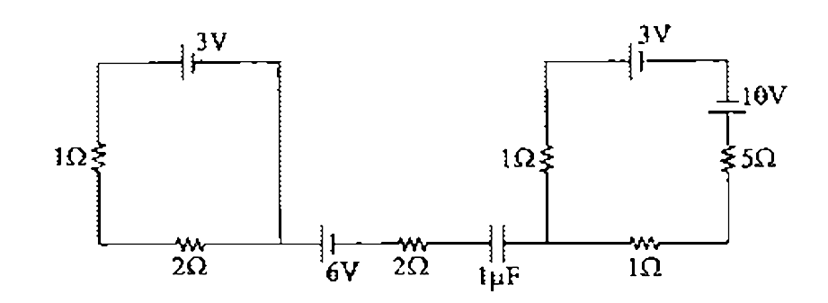
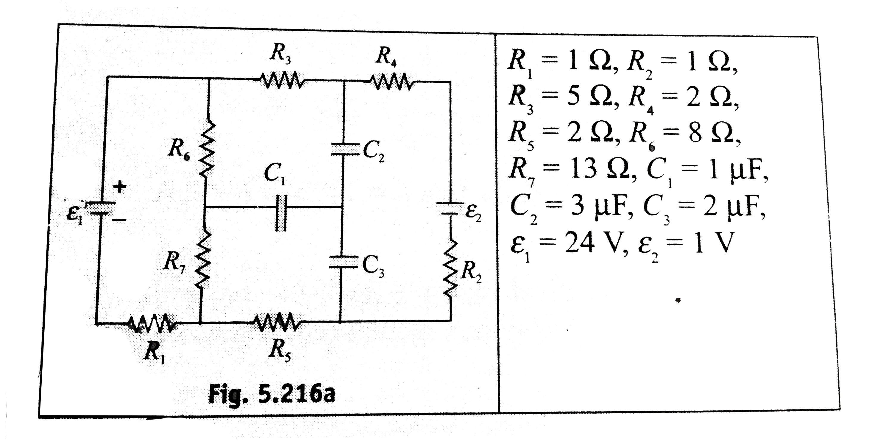
In the circuit shown in fig calculate chare on capacitors C1 and C2 in steady stete.
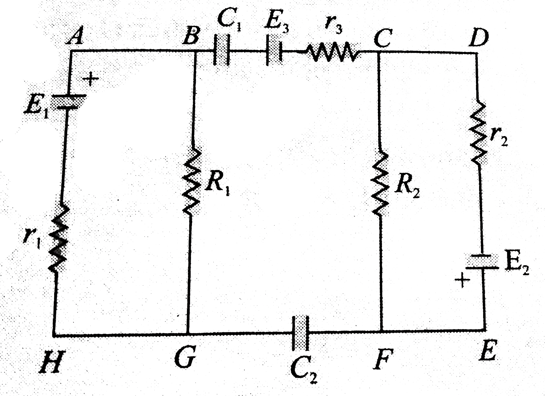
Video Solution
Text Solution
In steady no current flows thorugh capacitors,
therefore, there are four unkonw quantites in the given
circuit .
I. curretn in left mesh ABGHA
ii. Curent in rieght mesh CDEFC
iii. Charge q−1 on capcitor C2
iv. Charge q-2 on capactor C2
But by applyingh Kirchhoff's voltage law, three unique
equations can be formed. At steady to current passes
through capacitor branches. In an isolated system, net charge
should be zero, i.e the sum of charges on plates in zero. Hence,
charge on both capacitors should be equal. So
q1=q2=a(say)
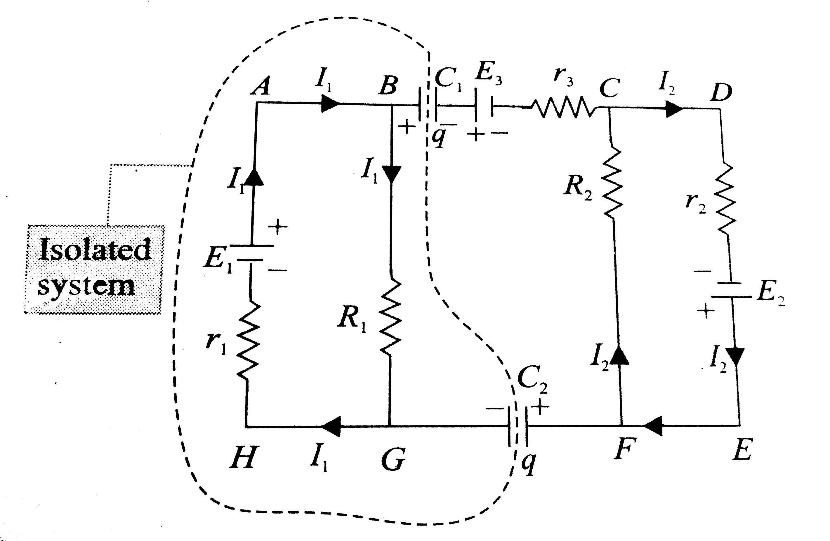
Considering this fact, in steady state, circuit will be as
shown in Applying Kirchhoff's voltage law in
mesh ABGHA, we get
I1R1+I1r1−E1=0orI1=0.5A
For mesh CDEFC,
I2r2+I1R2=0orI2=3A
Now applying Kirchhoff's voltage law in mesh BCFGB, we
get
+qC1+E3_I2R2+qC2=I1R1=0
or q=10μC
|
Topper's Solved these Questions
- ELECTRIC CURRENT AND CIRCUITBOOK - CENGAGE PHYSICSCHAPTER - ELECTRIC CURRENT AND CIRCUITEXERCISE - Exercise 5.1
28 Videos
- ELECTRIC CURRENT AND CIRCUITBOOK - CENGAGE PHYSICSCHAPTER - ELECTRIC CURRENT AND CIRCUITEXERCISE - Exercise 5.2
50 Videos
- ELECTRIC CURRENT AND CIRCUITBOOK - CENGAGE PHYSICSCHAPTER - ELECTRIC CURRENT AND CIRCUITEXERCISE - Interger
8 Videos
- ELECTRIC CURRENT & CIRCUITSBOOK - CENGAGE PHYSICSCHAPTER - ELECTRIC CURRENT & CIRCUITSEXERCISE - Kirchhoff s law and simple circuits
15 Videos
- ELECTRIC FLUX AND GAUSS LAWBOOK - CENGAGE PHYSICSCHAPTER - ELECTRIC FLUX AND GAUSS LAWEXERCISE - MCQ s
38 Videos
Similar Questions
Knowledge Check
Consider the circuit shown in the figure. Find the charge on capacitor C between A and D in steady state.
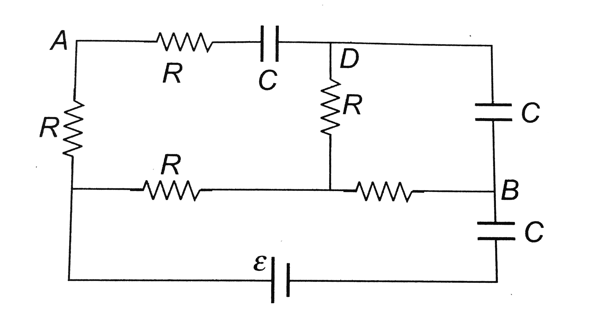 ACεBCε/2CCε/3Dzero
For the circuit shown in the figure, find the charge stored on capacitor in steady state.
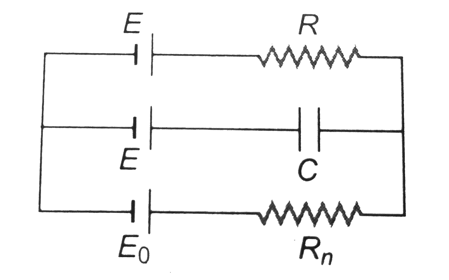 ARCR+R0EBRCR0E−E0CzeroDRCR+R0(E−E0)
For the circuit shown in the figure determine the charge on capacitor in steady state.
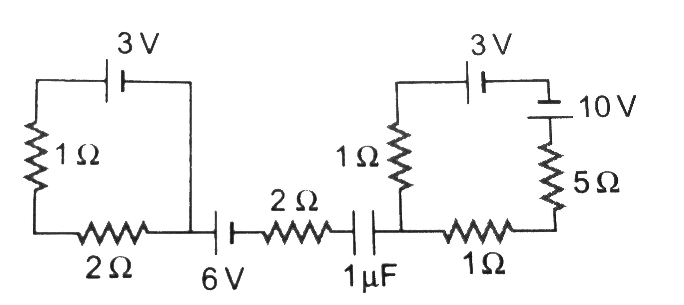 A4μCB6μCC1μCDzero
In the circuit shown in figure. The charge on capacitor C2 in steady state is 10xμC. Find the value of x.
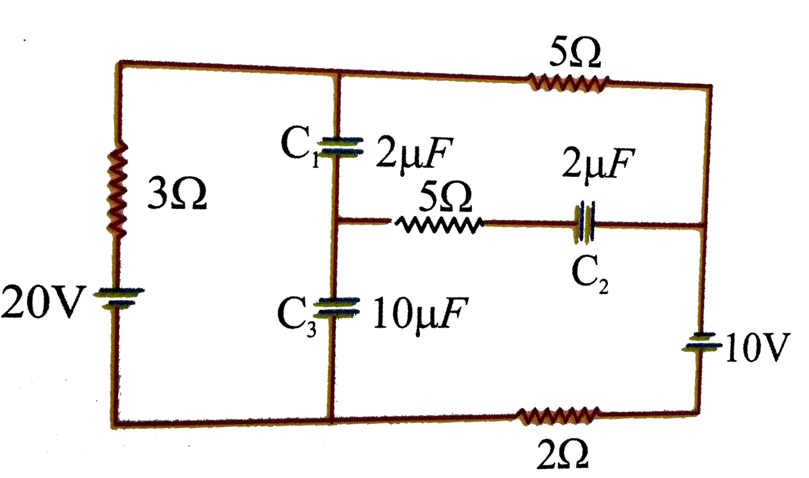 .
.
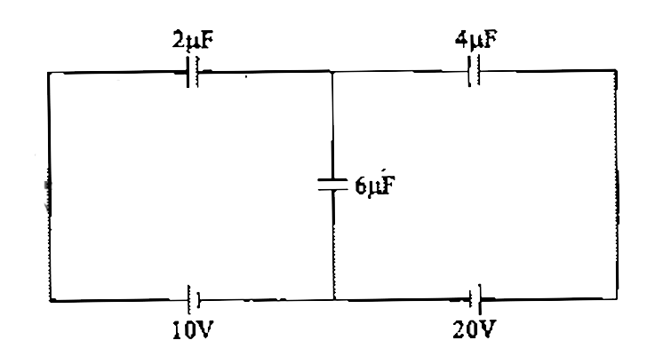
View SolutionIn the circuit shown in figure find the charges on the three capacitors in steady state.
View SolutionIn the circuit shown in the figure K_(1) is open.The charge on capacitor C in steady state is q_(1) .Now key is closed and at steady state charge on C is q_(2) . The ratio of charges q_(1)/q_(2) is qquad R_(1)=2Omega E
View SolutionAnalyze the circuit find the charge in capactiors C1C2, and C3 n steady state.
View SolutionThe circuit is in a steady state.
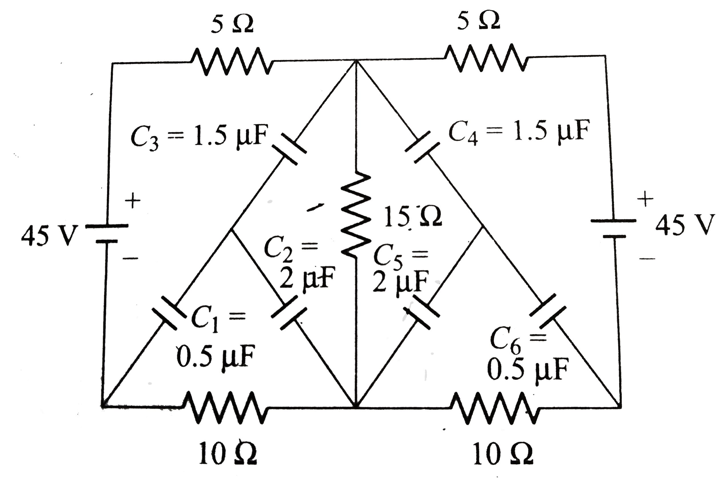
The charge in capacitor C1 is
View Solution

