A charged capacitor C1 is discharged through a resistance R by putting switch S in position 1 of the circuit as shown in fig.5.201. when the discharge current reduces to iω, the switch is sudenly shifted to position 2. Calculate the amount of heat liberated in resistor R starting form this instant. Also calculate current I through the circuit as a function of time.
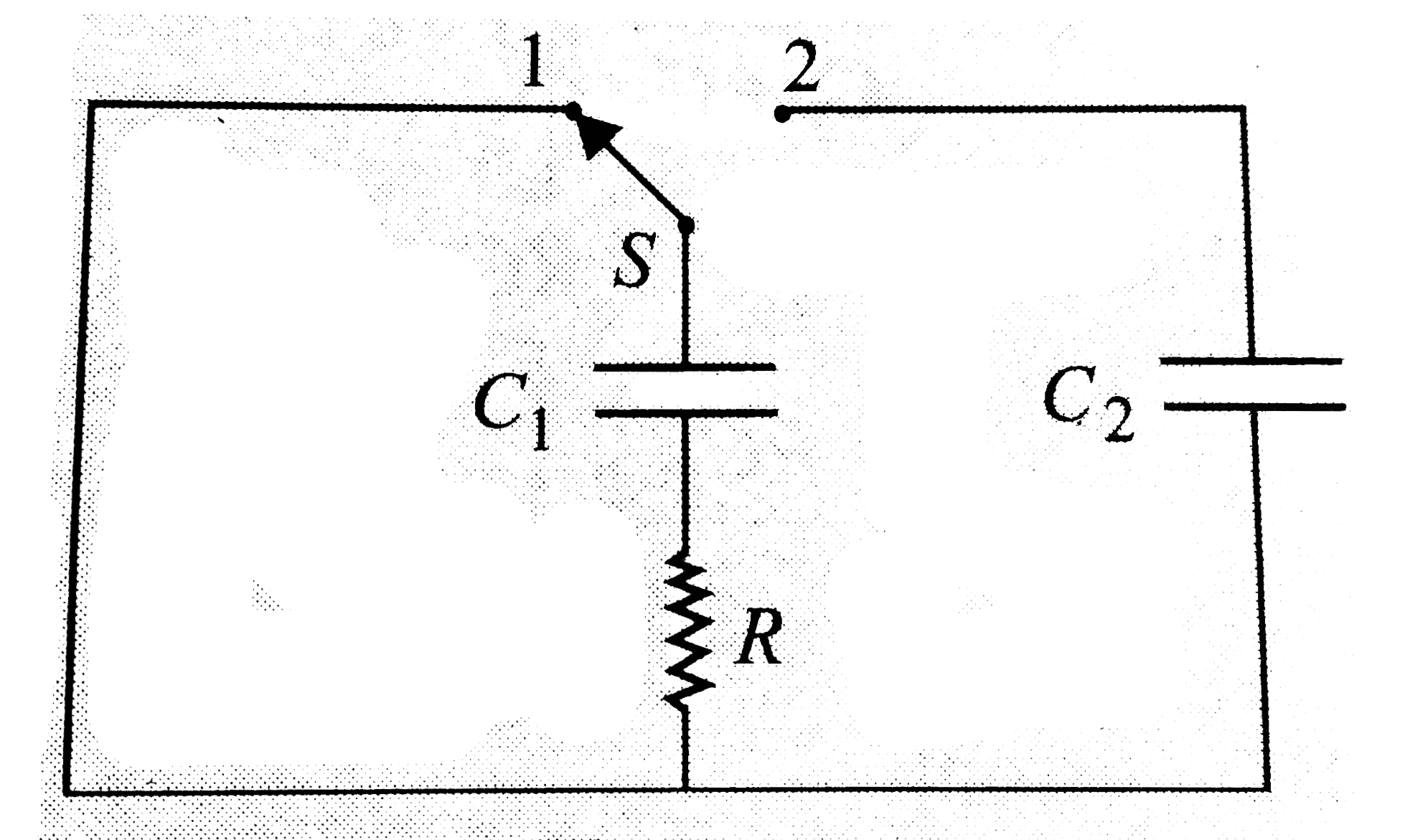
Let the charge on capacitor C1beq0 when the switch was
shifted from position 1 to position 2. just before shifting of
switch, the circuit was as shown in fig 5.202

q0C1−I0R=0orq0=I0RC1
When the switch is shifted from position 1 to 2,
the capacitor C1 continues to be discharged while C2 starts
charging. Let at time t, after shiffting of switch to position 2,
charge on capacitor C2 be q and let current through the circuit
be I.
Therefore, charge remaining on C1 is equal to (q0−q) as
shown in fig 5.202 (b). Applying Kirchhoff's voltage law on
the circuit shown in fig. 5.202 (b) we get
qC2+IR−(q0−q)C1=0
or IR=q0−qC1−qC2=(q0C2−qC2)−qC1C1C2
But current , I=dqdt (rate of increase of chargen C2
or R=dpdt=q0C2−q(C1+C2)C1C2
or dpq0C2−q(C1+C2)=dtRC1×C2
But at t = 0, q= 0,
∫q0dqq0C2−q(C1+C2)=∫10dtRC1C2
From the above equation, we get
q=(q0C2C1+C2)[1−e−(C1+C2RC1C2)t]
Substituting q0=I0RC1, we get
q=I0RC1C2C1+C2[1−e−(C1+C2RC1C2)t]
But current
I=dqdt=I0e−C1+C2RC1C2t
in a steady state, the common potential difference across
capacitors is given by
V=q0+0C1+C2=I0RC1C1+C2(using V=C1V1+C2V2C1+C2)
Initially energy stored in C1 was
U1=q202C1=12I20R2C1
In steady state, energy stored in two capacitors is
U2=12C1V2+12C2V2=12(C1+C2)I20R2C21(C1+C2)2=I20R2C212(C1+C2)
Heat generated across resistor R is equal to the loss of
energy stored ni capacitors during redistribution of charge, i.e.,
U1=U2=I20R2C1C22(C1+C2)
Topper's Solved these Questions
- ELECTRIC CURRENT AND CIRCUITBOOK - CENGAGE PHYSICSCHAPTER - ELECTRIC CURRENT AND CIRCUITEXERCISE - Exercise 5.1
28 Videos
- ELECTRIC CURRENT AND CIRCUITBOOK - CENGAGE PHYSICSCHAPTER - ELECTRIC CURRENT AND CIRCUITEXERCISE - Exercise 5.2
50 Videos
- ELECTRIC CURRENT AND CIRCUITBOOK - CENGAGE PHYSICSCHAPTER - ELECTRIC CURRENT AND CIRCUITEXERCISE - Interger
8 Videos
- ELECTRIC CURRENT & CIRCUITSBOOK - CENGAGE PHYSICSCHAPTER - ELECTRIC CURRENT & CIRCUITSEXERCISE - Kirchhoff s law and simple circuits
15 Videos
- ELECTRIC FLUX AND GAUSS LAWBOOK - CENGAGE PHYSICSCHAPTER - ELECTRIC FLUX AND GAUSS LAWEXERCISE - MCQ s
38 Videos
Similar Questions
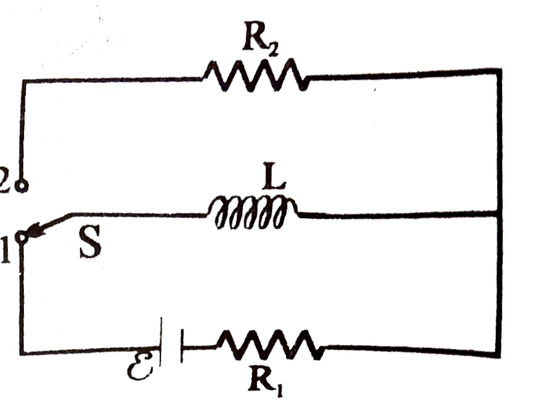
In the circuit shown, initially the switch is in position 1 for a long time. Then the switch is shifted to position 2 for a long time. Find the total heat produced in R2
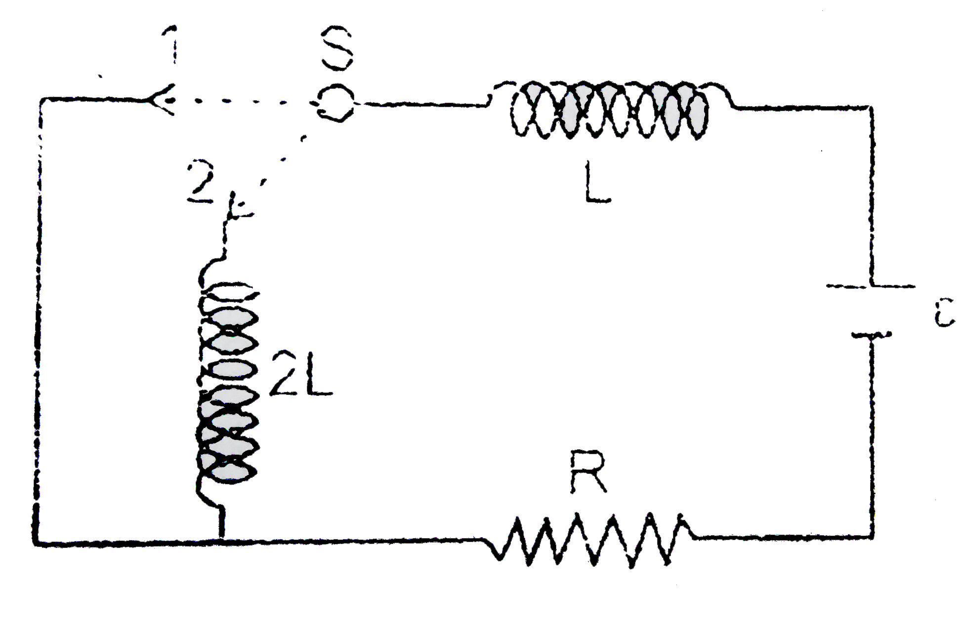
View SolutionIn the circuit shown, the switch S is shifted to position 2 from position 1 at t=0, having been in position 1 for a long time.Find the current in the circuit as a function of time.
View Solution
Knowledge Check
When a capacitor discharges through a resistance R, the time constant is τ and the maximum current in the circuit is i0
AThe initial charge on the capacitor was i0τBThe initial charge on the capacitor was 12i0τCThe initial energy stored in the capacitor was i20τDThe initial energy stored in the capacitor was 12i20RτWhen a capacitor discharges through a resistance R, the time constant is τ and the maximum current in the circuit is i0. Then,
Athe initial charge on the capacitor was i0τBthe initial charge on the capacitor was 12i0τCthe initial energy stored in the capacitor was t20RτDthe initial energy stored in the capacitor was 12t20RτIn the circuit shown in figure switch S is thrown to position 1 at t=0. when the current in the resistor is 1A, it is shifted to position 2. the total heat generated in the circuit after shifting to position 2 is
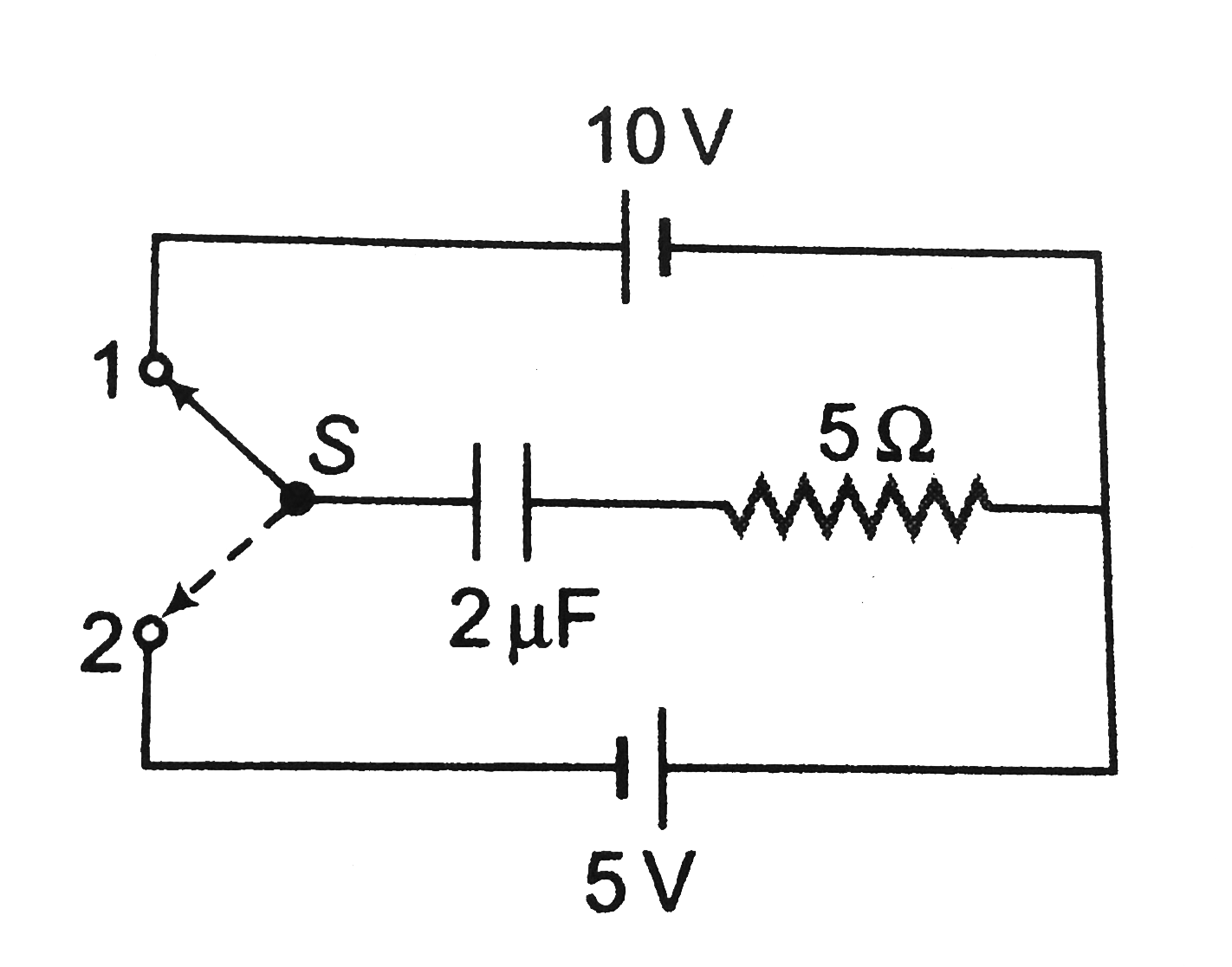 AzeroB625μJC100μJDnone of these
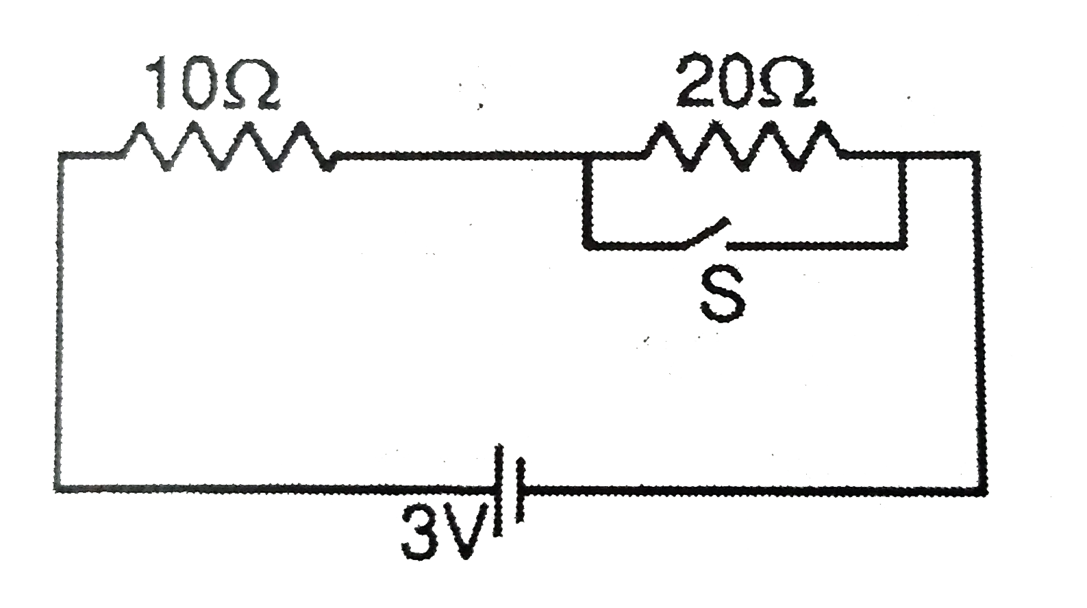
Consider the circuit shown in figure.Find the current through the10(Ω)resistor when the switch S is (a)open (b)closed .
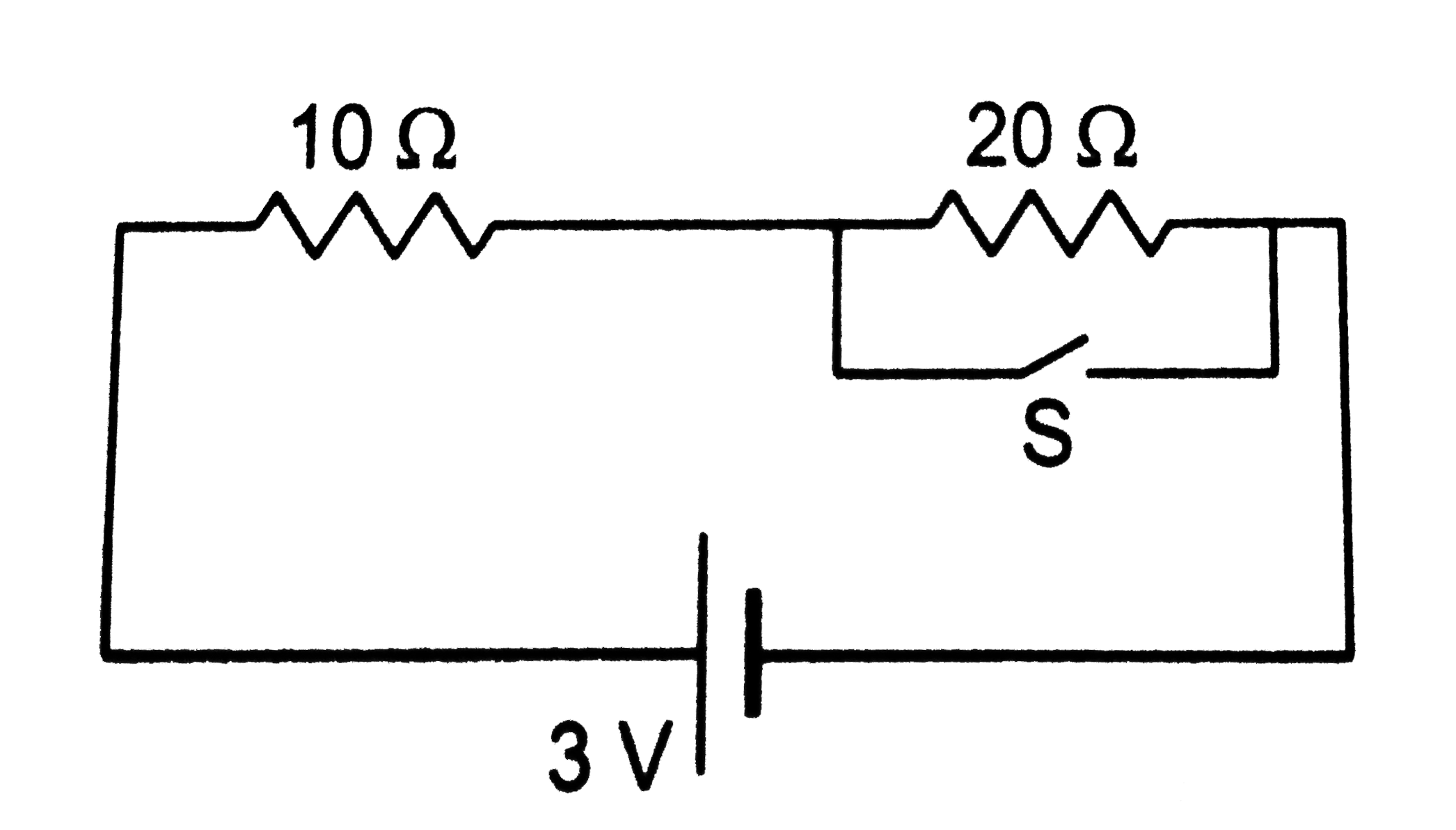
View SolutionConsider the circuit shown in figure. Find the current through the 10Ω resistor when the switch S is (a) opened (b) closed.
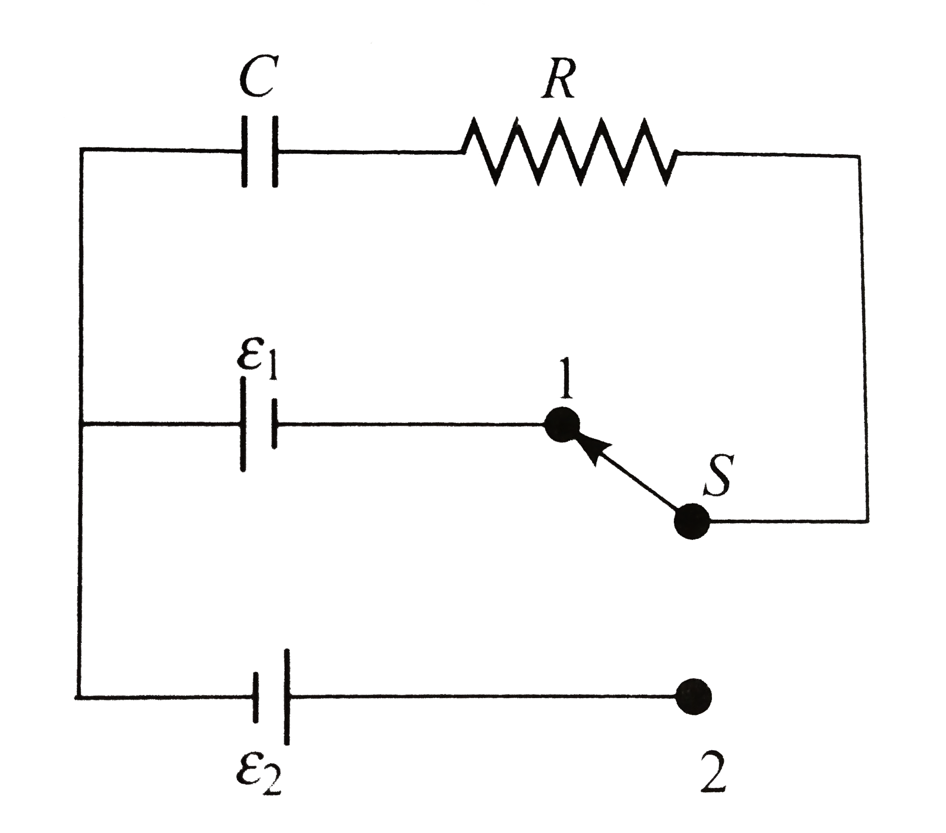
View SolutionA capacitor of capacitance C1=0.1F is charged by a battery of EMF E1=100V and internal resistance r1=1Ω by putting switch S in position 1 as shown in figure 3.257.

(a) Calculate heat generated across R=99Ω resistor during charging of capacitor.
(b) Now the switch is thrown to position 2 at instant t=0, calculate current I(l) through the circuit, consisting of capacitor and battery of EMFE2=50V and internal resistance r2=1Ω.
(c) Calculate heat generated in 50V battery.
View SolutionInitially, switch S is connected to position 1 for a long time . The net amount of heat generated in the circuit after it is shifted to position 2 is .
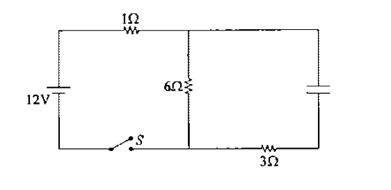
View SolutionIn the circuit shown in figure-3.348 when the switch is closed, the initial current through the 1Ω resistor just after closing the switch is
View Solution
