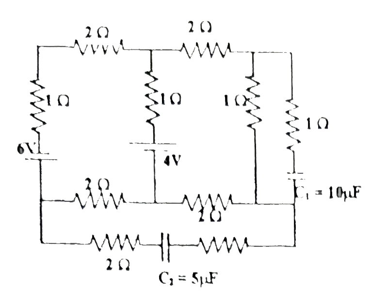
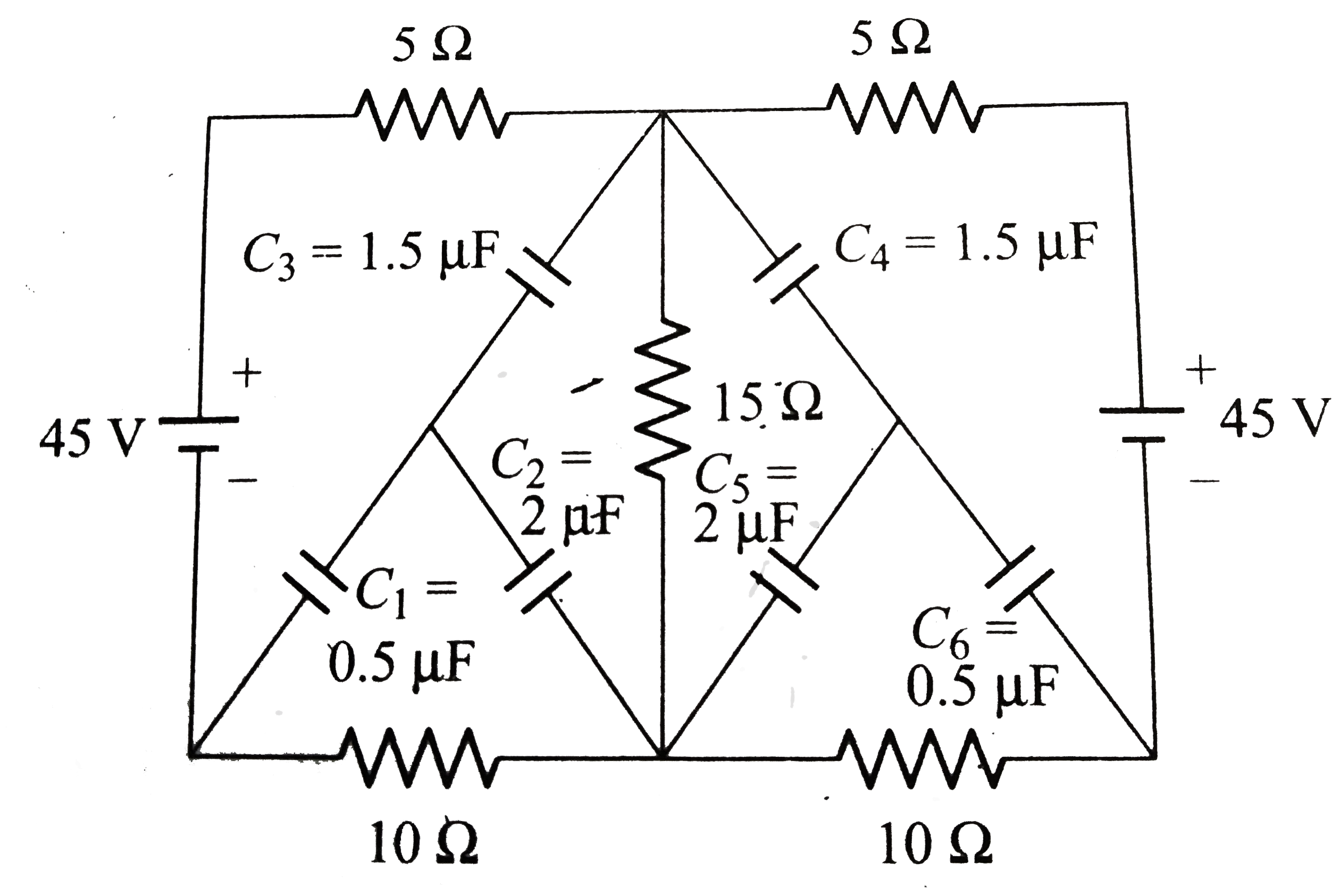
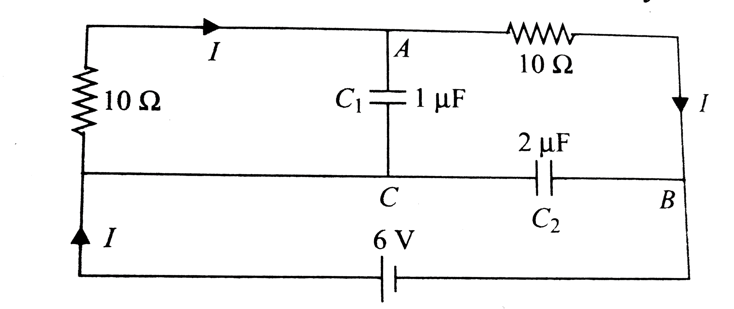
The circuit is in a steady state.
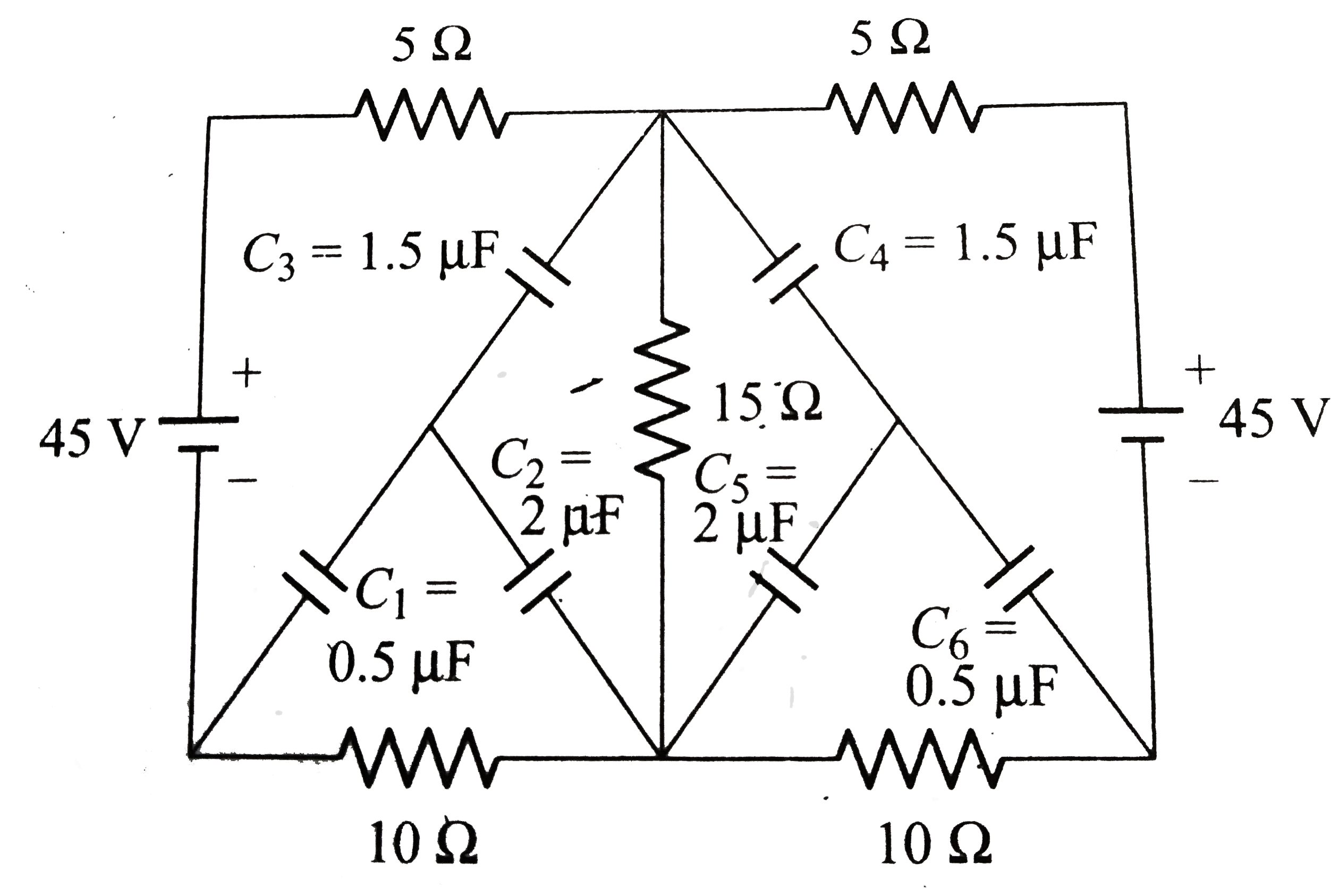
The charge in capacitor C1 is
A
20μC
B
30μC
C
40μC
D
10μC
Video Solution
Text Solution
The correct Answer is:D
d. At steady state, the circuit will be simplified to the following circuit :
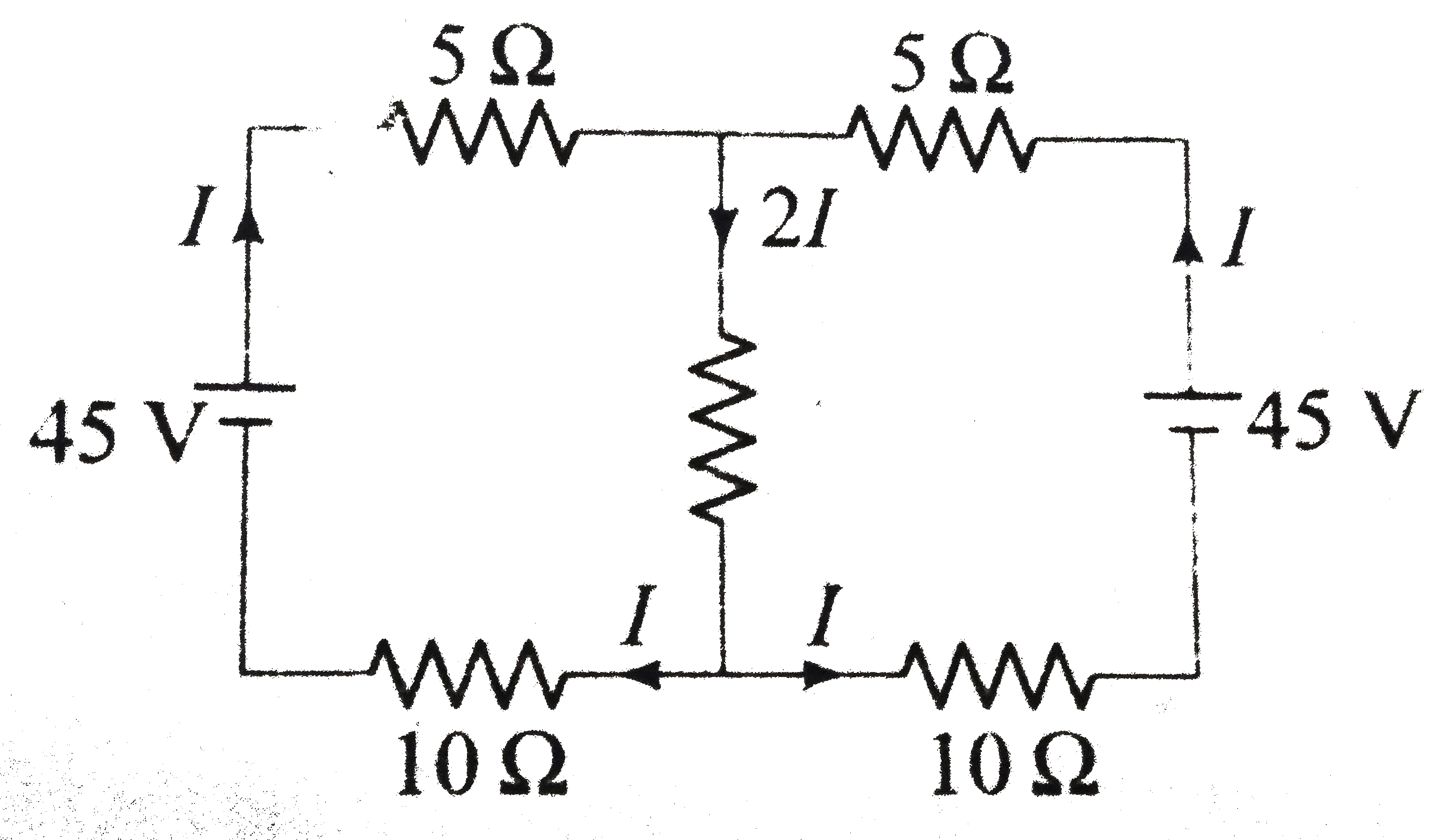
Using Kirchhoff's law, we can
calculate I=1A .
Further using Kirchhoff's law in
original circuit, we can calculate
charges on different capacitors.
|
Topper's Solved these Questions
- MISCELLANEOUS VOLUME 3BOOK - CENGAGE PHYSICSCHAPTER - MISCELLANEOUS VOLUME 3EXERCISE - Interger Answer type
20 Videos
- MISCELLANEOUS VOLUME 3BOOK - CENGAGE PHYSICSCHAPTER - MISCELLANEOUS VOLUME 3EXERCISE - Fill in the blanks
10 Videos
- MISCELLANEOUS VOLUME 3BOOK - CENGAGE PHYSICSCHAPTER - MISCELLANEOUS VOLUME 3EXERCISE - Assertion and Reason Type
8 Videos
- MECHANICAL PROPERTIES OF SOLIDSBOOK - CENGAGE PHYSICSCHAPTER - MECHANICAL PROPERTIES OF SOLIDSEXERCISE - Question Bank
4 Videos
- MISCELLANEOUS VOLUME 5BOOK - CENGAGE PHYSICSCHAPTER - MISCELLANEOUS VOLUME 5EXERCISE - Integer
12 Videos
Similar Questions
Knowledge Check
The circuit is in a steady state.
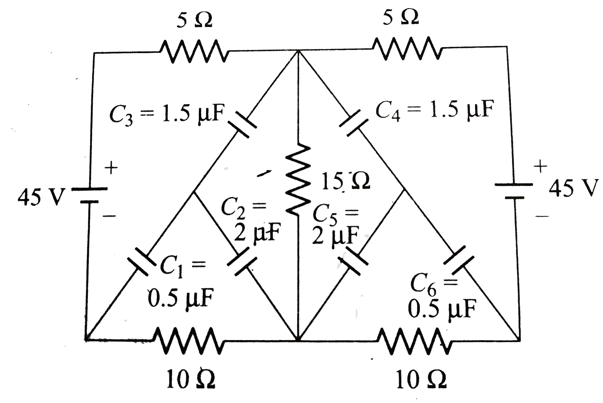
The charge in capacitor C3 isA10μCB30μCC20μCD40μCThe circuit is in a steady state.
The charge in capacitor C2 isA30μCB10μCC20μCD40μCConsider the circuit shwon in fig. The circuit is in steady state.
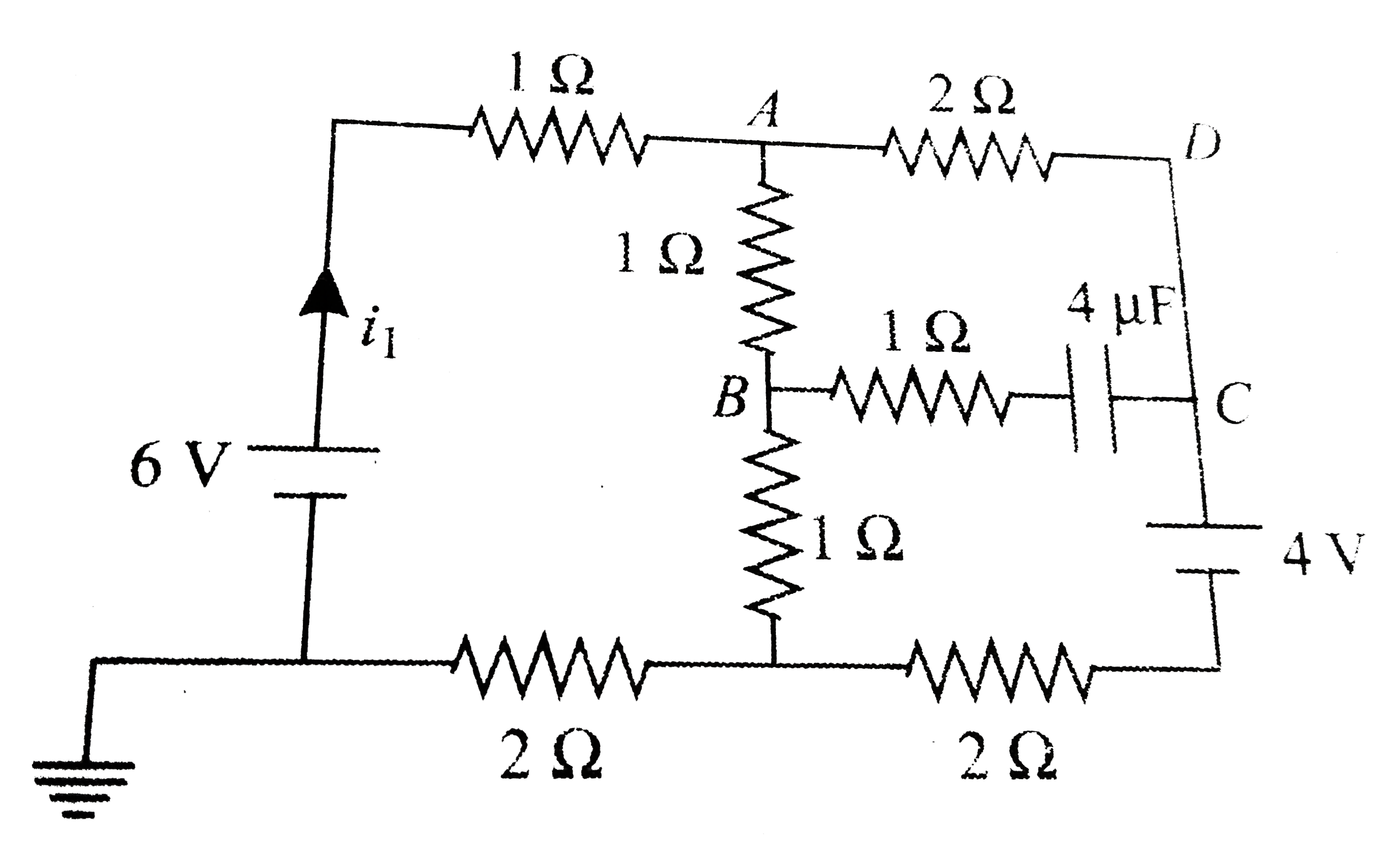
The charge in capacitor isA2μCB4μCC6μCD8μC
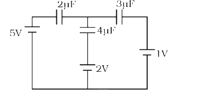
In steady state, find the charge on 3μF capacitor in μC
View SolutionThe circuit shown in fig 5.223 is in steady state.
find the charges on the capacitors C1andC2 respectively.
View SolutionThe figure shown is part of the circuit at steady state

The charge on 2μF capacitor is :
View SolutionIn the circuit shown in the figure, in steady state:

The charge on 5μF capacitor is
View SolutionThe circuit consists of two resistors (of resistance R1=20Ω and R2=10Ω), a capacitor (of capacitance C=10μF) and two ideal cells. In the circuit shown the capacitor is in steady state and the switch S is open
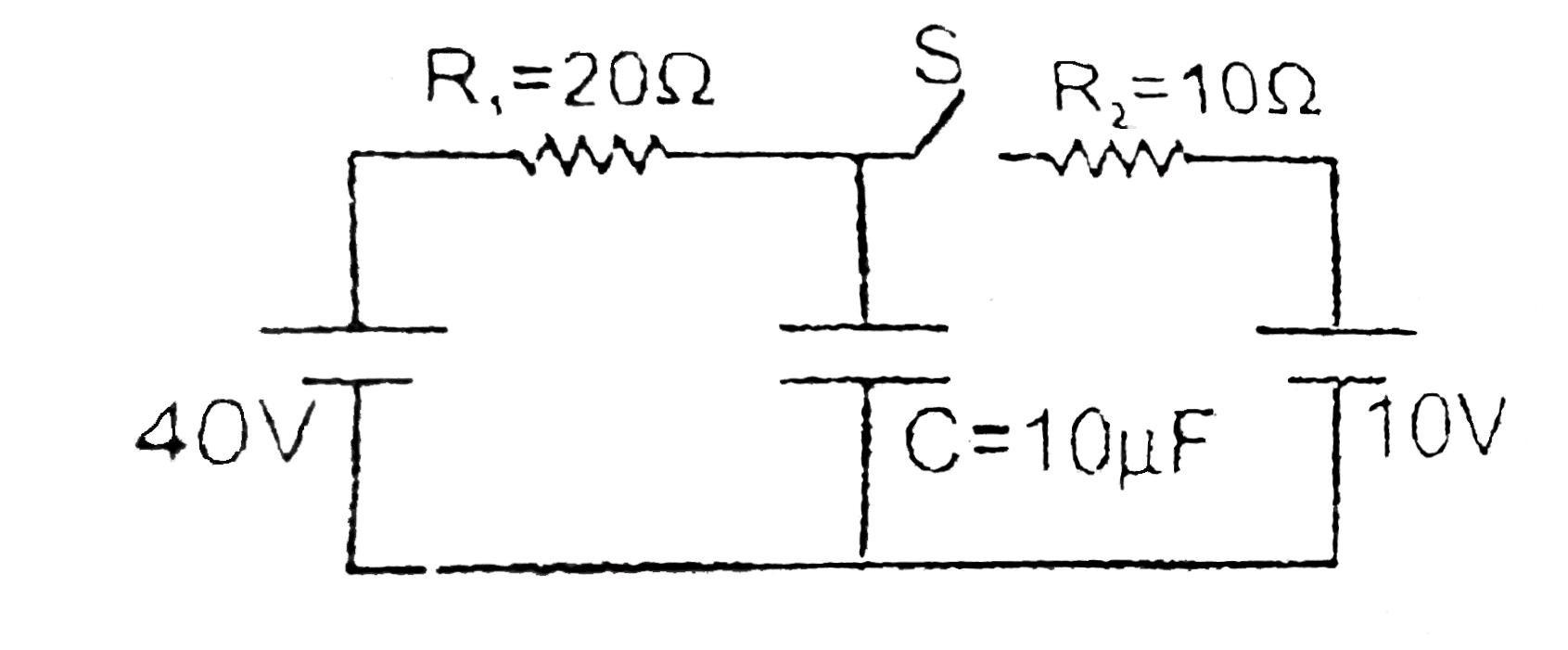
The charge on capacitor in steady state with switch S closed.
View Solution

