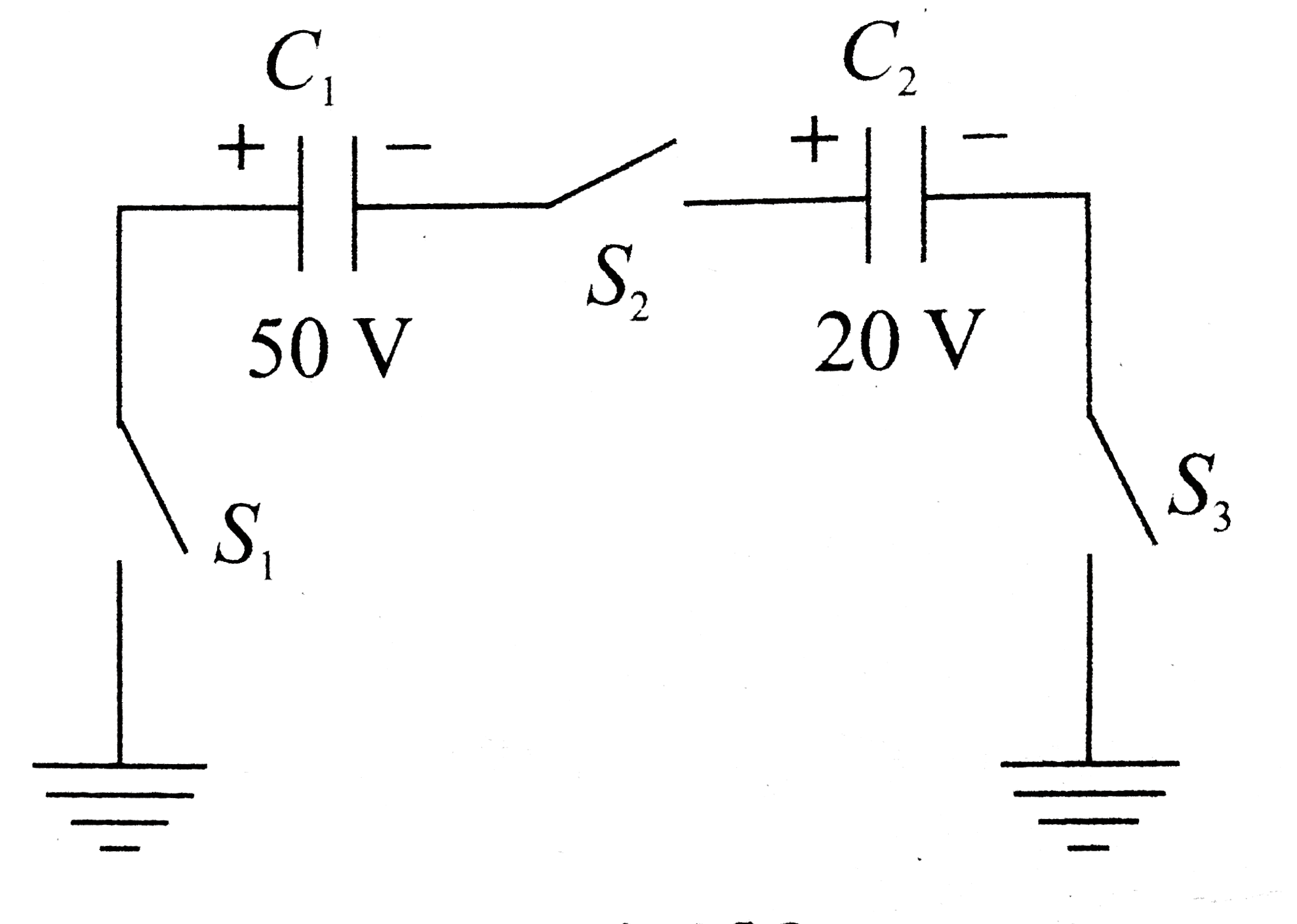
In the circuit shown, C1=C2=2μF. Capacitor C1 is charged to 50V and C1 is charge to 20V. After charging they are connected as shown. When S1,S2, and S3, are clsosed,
 .
.
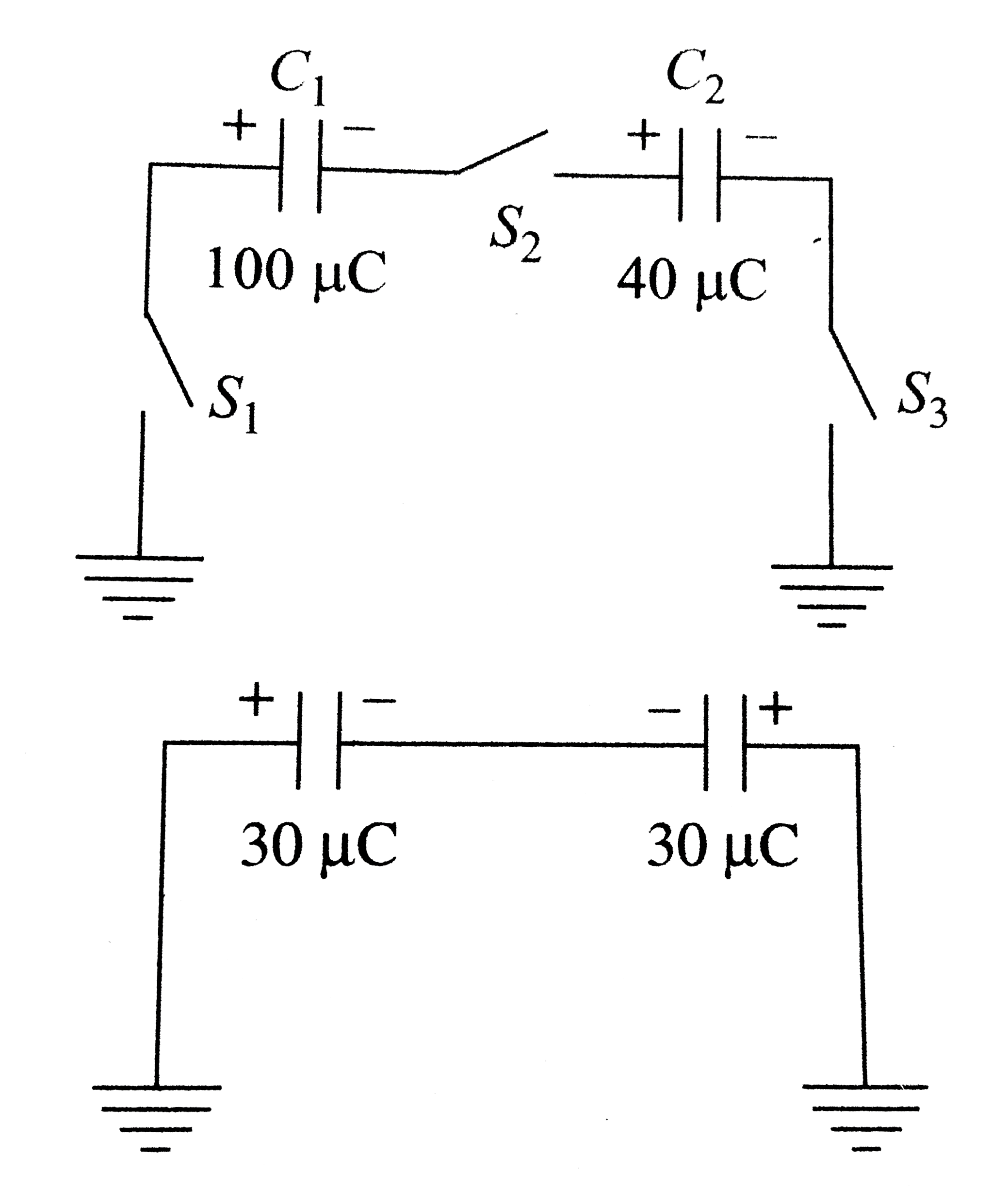
70μC of charge will pass through S1
100μC of chaarge will pass throuth S1
70μC of charge will pass throuth S3
40μC of chaarge will pass throuth S3.
The correct Answer is:A, C
When switches are open, charges on the capacitor are capacitor are shown. When switches are closed, capacitors become parallel, charges are shown on two capacitors. Comparing two diagrams, it is clear that 70μC of charge will pass through switches S1 and S3. Hence choices a and c are correct and choices b and d are wrong.
 .
.
Topper's Solved these Questions
- CAPACITOR AND CAPACITANCEBook:CENGAGE PHYSICSChapter:CAPACITOR AND CAPACITANCEExercise:Comprhension
Explore 35 Videos
- CAPACITOR AND CAPACITANCEBook:CENGAGE PHYSICSChapter:CAPACITOR AND CAPACITANCEExercise:Integer
Explore 5 Videos
- CAPACITOR AND CAPACITANCEBook:CENGAGE PHYSICSChapter:CAPACITOR AND CAPACITANCEExercise:Single Correct
Explore 49 Videos
- ATOMSBook:CENGAGE PHYSICSChapter:ATOMSExercise:QUESTION BANK
Explore 40 Videos
- CENGAGE PHYSICS DPPBook:CENGAGE PHYSICSChapter:CENGAGE PHYSICS DPPExercise:subjective type
Explore 51 Videos
Similar Questions
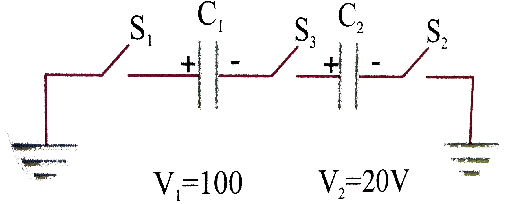
In the circuit shown in figure C1=1μF and C2=2μF. The capacitor C1 is charged to 100V and the capacitor C2 is charged to 20V. After charging then are connected as shown. When the switches S1,S2 and S3 are closed, the charged flowing through S1 is
 .
.
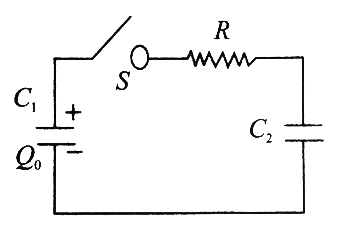
View SolutionIn the circuit shown, the capacitor C1 is initially charged with charge q0. The switch S is closed at time t = 0 . The charge on C2 after time t is
View Solution
Knowledge Check
In the circuit shown in figure C1=C2=2μF. Then charge stored in
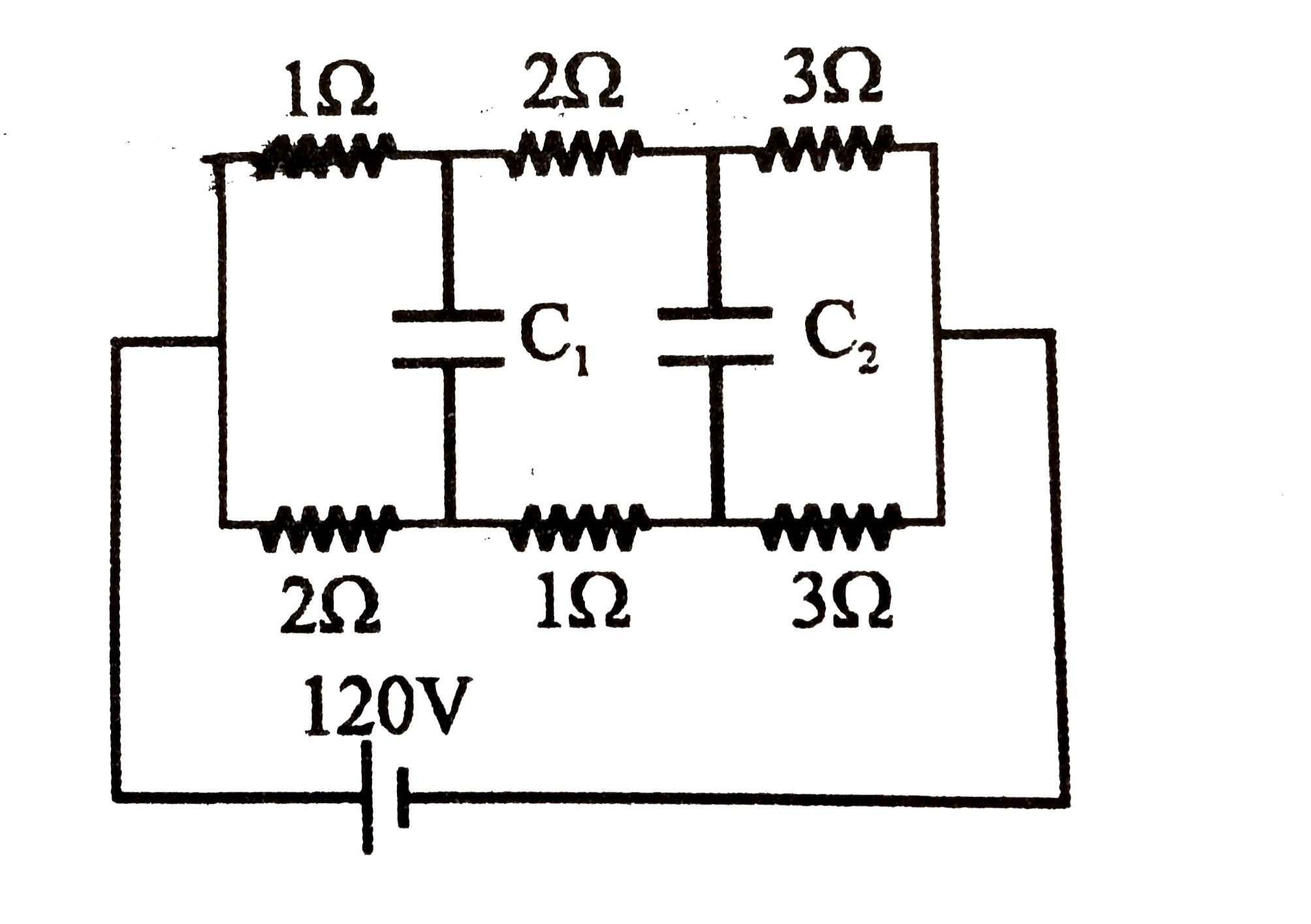 Acapacitor C1 is zeroBcapacitor C2 is zeroCboth capacitor is zeroDcapacitor C1 is 40μC
In the circuit shown in figure C1=2C2. Capacitance C1 is charged to a potential of V. The current in the circuit just after the switch S is closed is
 AzeroB2VRCinfiniteDV2R
In the circuit shown in fig. C1=2C2 Initially, capacitor C1 is charged to a potential of V. The current in the circuit just after the switch S is closed is
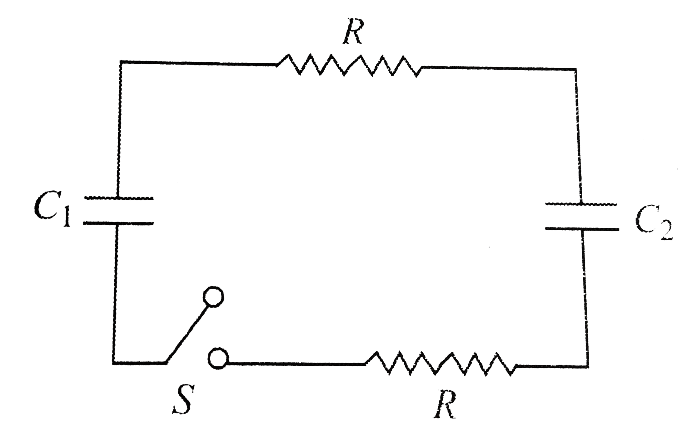 A0B2V/RC∞DV/2R
Consider the circuit shown where C1=6μF,C2=3μF and V=20V. Capacitor C1 is first charged by closing the switch S1. Switch S1 is then opened, and the charged capacitor is connected to the uncharged capacitor C2 by closing S2.
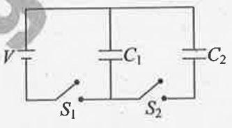
View SolutionTwo capacitors C1 and C2 are charged to same potential V, but with opposite polarity as shown in the figure. The switches S1 and S2 are then closed

View SolutionTwo capacitors of capacity 6μF and 3 muFarechar≥100 Vand50 Vseparatelyandco∩ectedasshown∈NowallthethreeswitchesS_(1),S_(2),andS_(3) are closed.
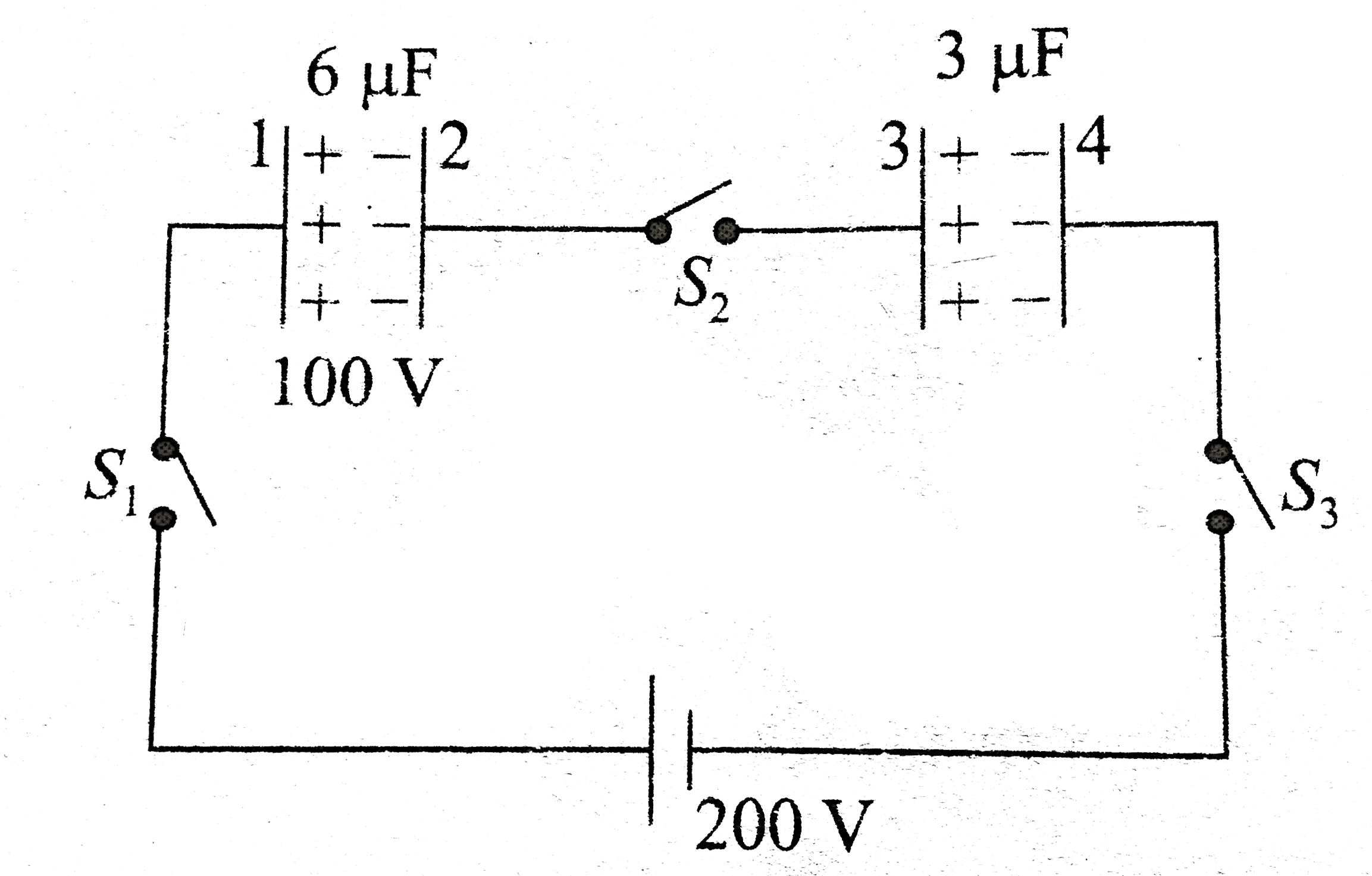
Which plates form an isolated system?
View SolutionIn the figure shown C1=1F,C2=2FandL=5H. Initially C1 is charged 50V and C2 to 10V. Switch S is closed at time t=D. Suppose at some instant charge on C1 is 20C with the same polarties as shown in the figure
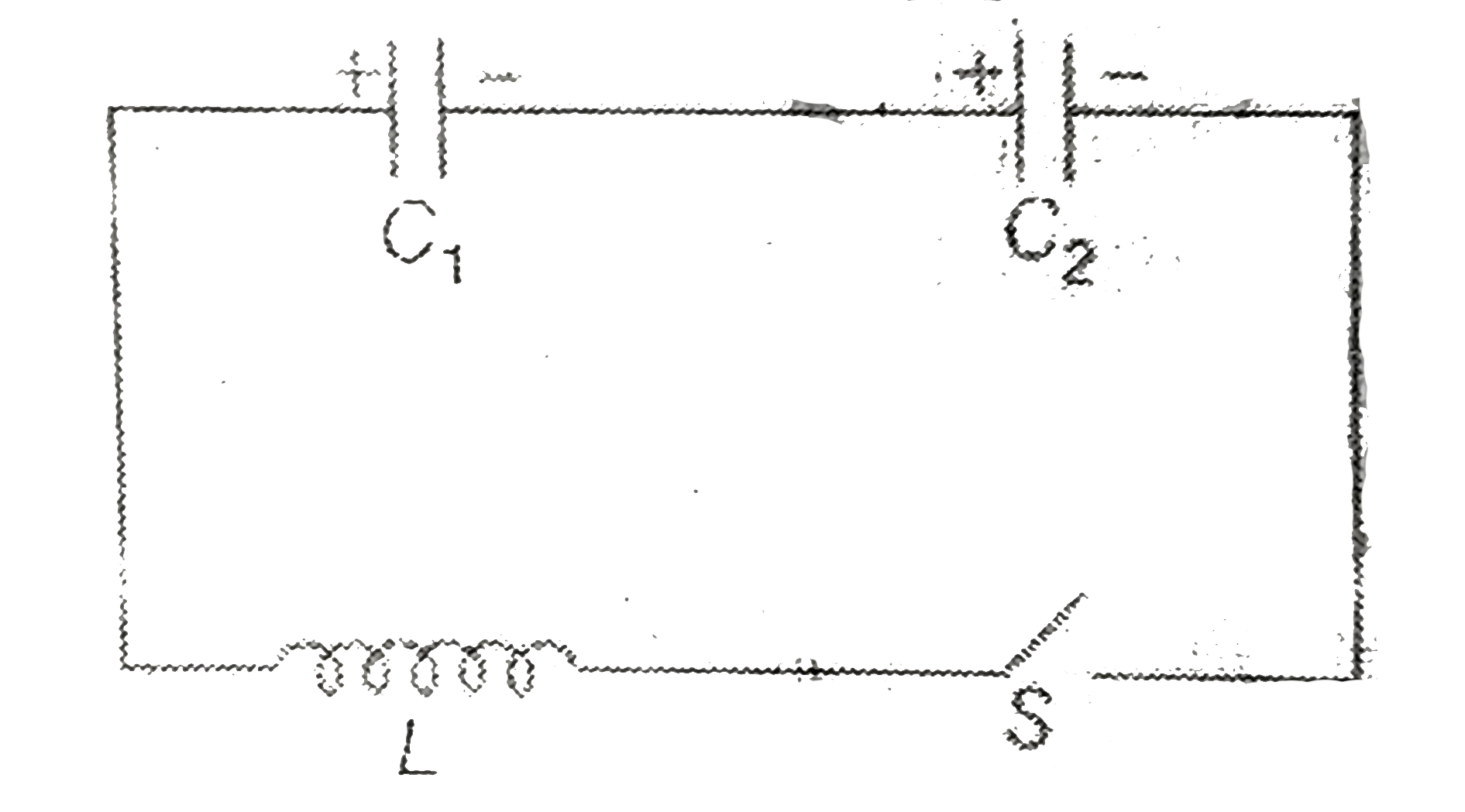
Energy stored in capacitor C2 at this instant will
View SolutionIn the figure shown C1=1F,C2=2FandL=5H. Initially C1 is charged 50V and C2 to 10V. Switch S is closed at time t=D. Suppose at some instant charge on C1 is 20C with the same polarties as shown in the figure
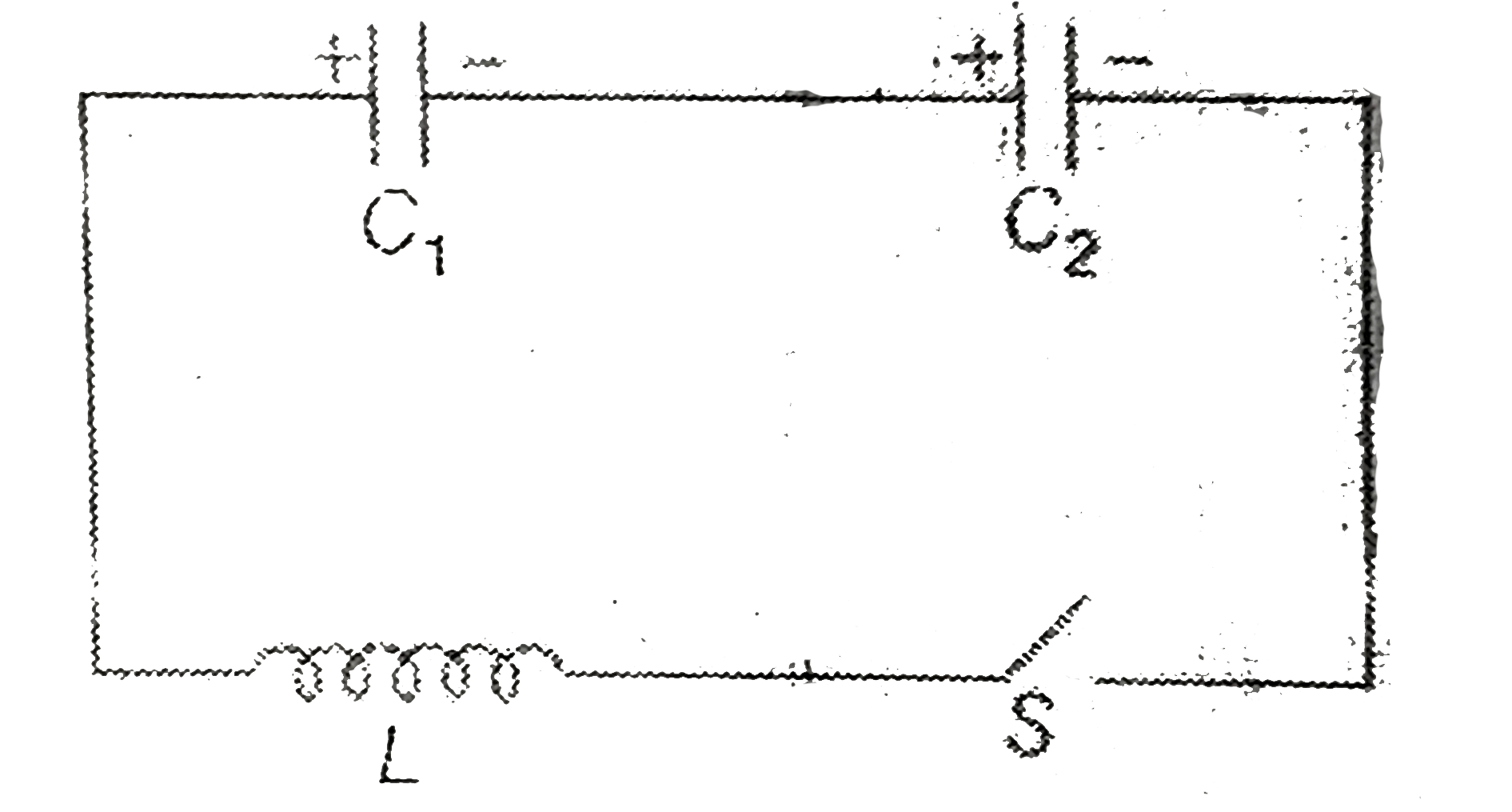
Current in the circuit at this instant will be
View Solution

