In the circuit shown in figureure, the reading of the AC ammeter is
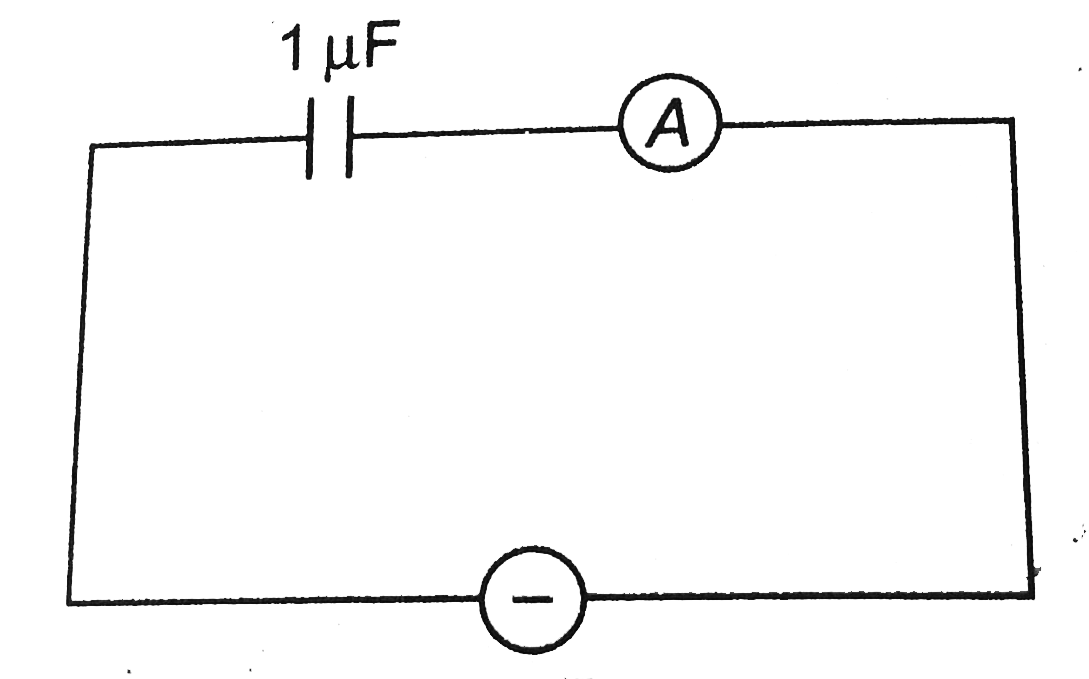 .
.
A
20√2mA
B
40√2mA
C
20mA
D
40mA
Video Solution
Text Solution
The correct Answer is:C
XC=1ωC=1100×10−6=104Ω
Irms=VrmsXC=(200√2/√2)104
=0.02A=20mA.
|
Topper's Solved these Questions
- ALTERNATING CURRENTBOOK - DC PANDEYCHAPTER - ALTERNATING CURRENTEXERCISE - Level - 1 Subjective
6 Videos
- ALTERNATING CURRENTBOOK - DC PANDEYCHAPTER - ALTERNATING CURRENTEXERCISE - Level- 2 Single Correct
18 Videos
- ALTERNATING CURRENTBOOK - DC PANDEYCHAPTER - ALTERNATING CURRENTEXERCISE - Level 1 Assertion-Reason
11 Videos
- ATOMSBOOK - DC PANDEYCHAPTER - ATOMSEXERCISE - MEDICAL ENTRANCES GALLERY
42 Videos
Similar Questions
Knowledge Check
In the circuit shown in figure, reading of ammeter will
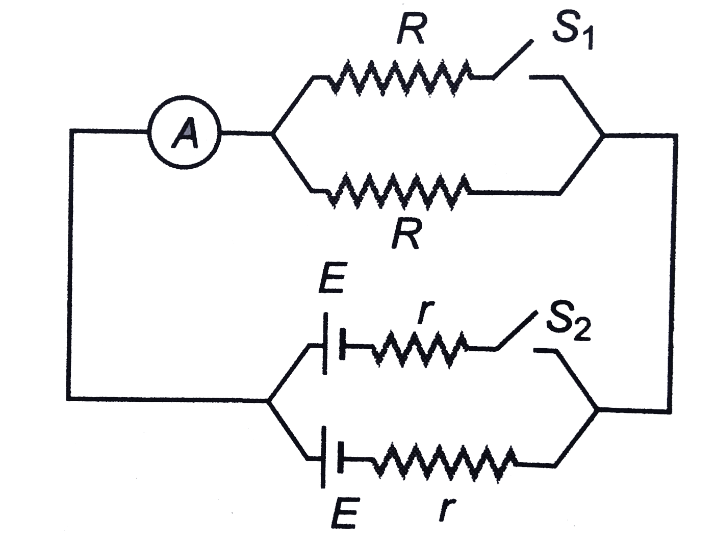 Ashows no deflection if S1 is closedBdecrease if S2 is closedCincrease if S2 is closedDdecrease if S2 is closed
In the circuit shown in figure the reading of ammeter is the same with both switches open as with both closed. Then find the resistance R. (ammeter is ideal).
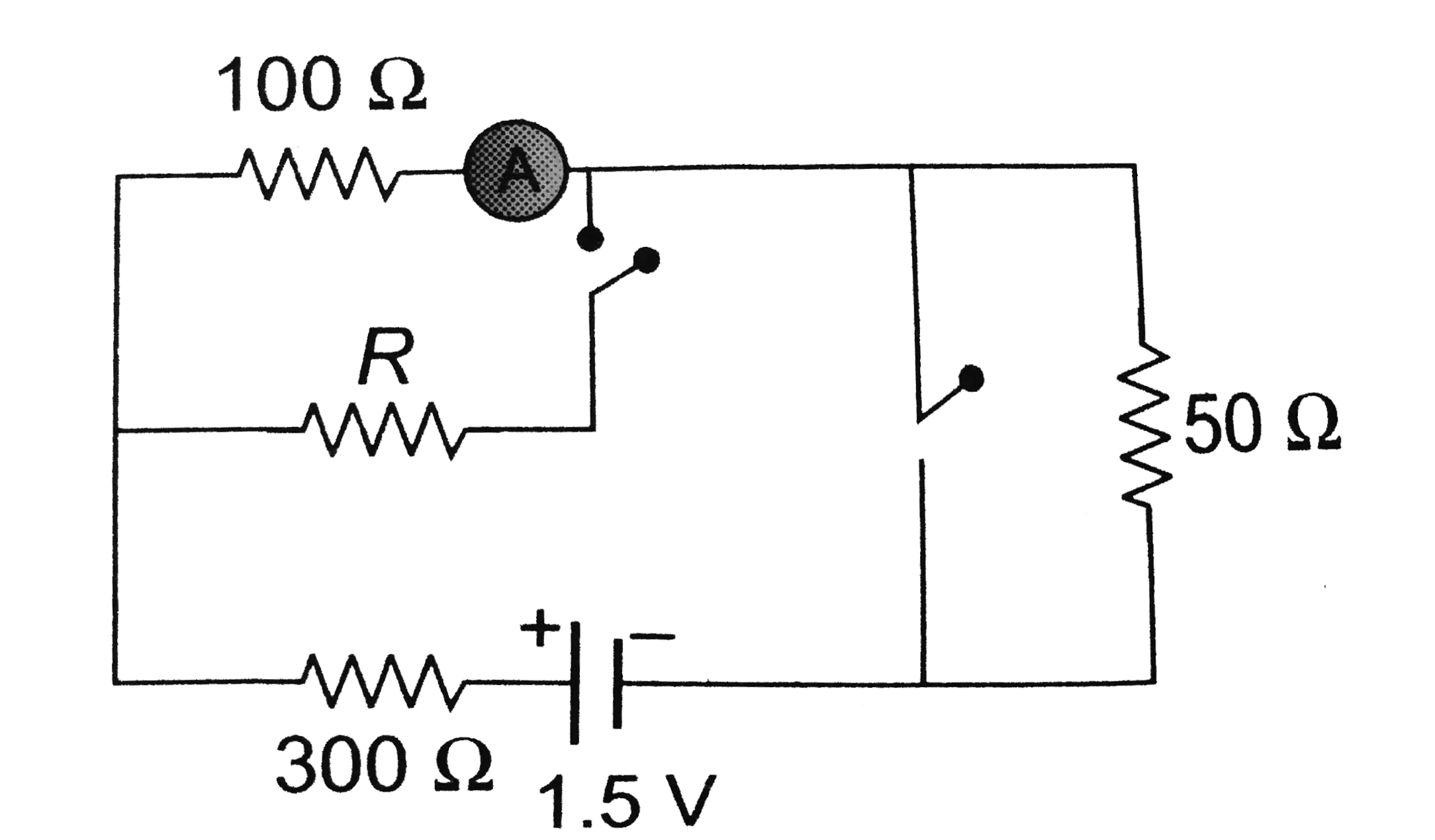 A550ΩB400ΩC350ΩD600Ω
In the circuit shown in figureure, the power consumed is
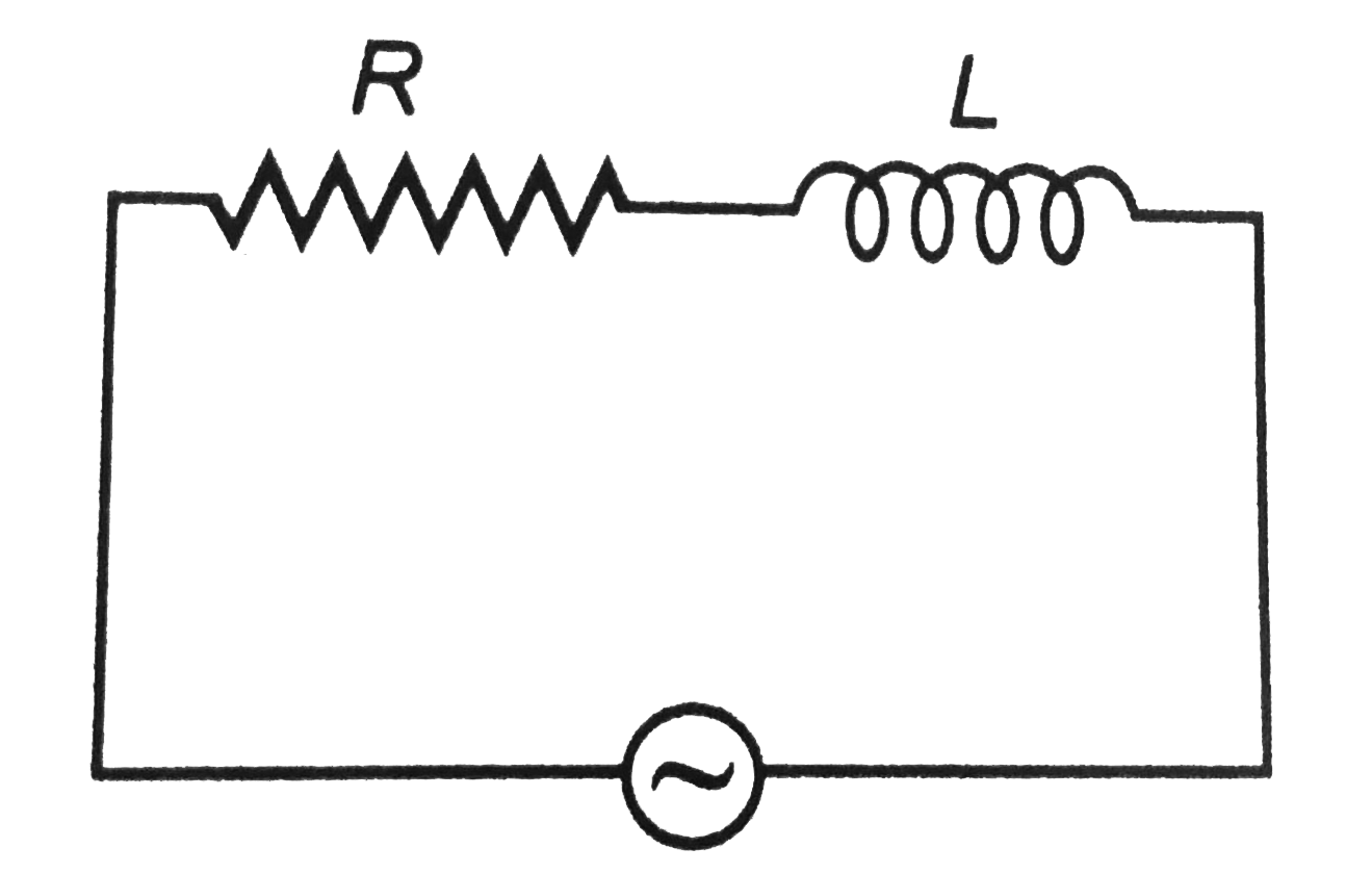 .AzeroBV202RCV20R2(R2+ω2L2)Dnone of these
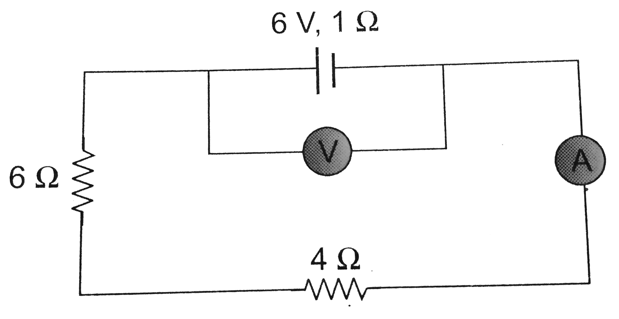
In the circuit shown in figure, what will be the readings of voltmeter and ammeter?
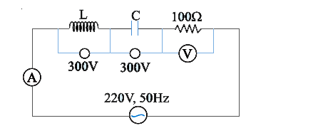
View SolutionIn the circuit shown, the reading of the ammeter if diode is not ideal, will be

View SolutionIn the circuit shown, the reading of ammeter is:
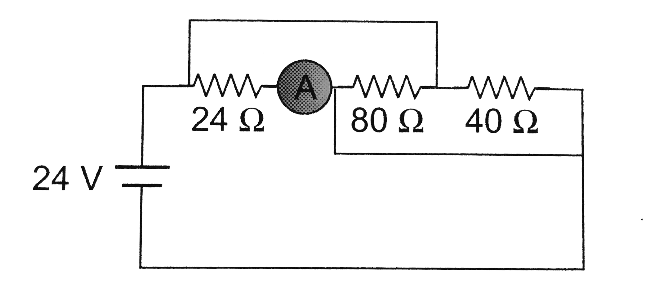
View Solution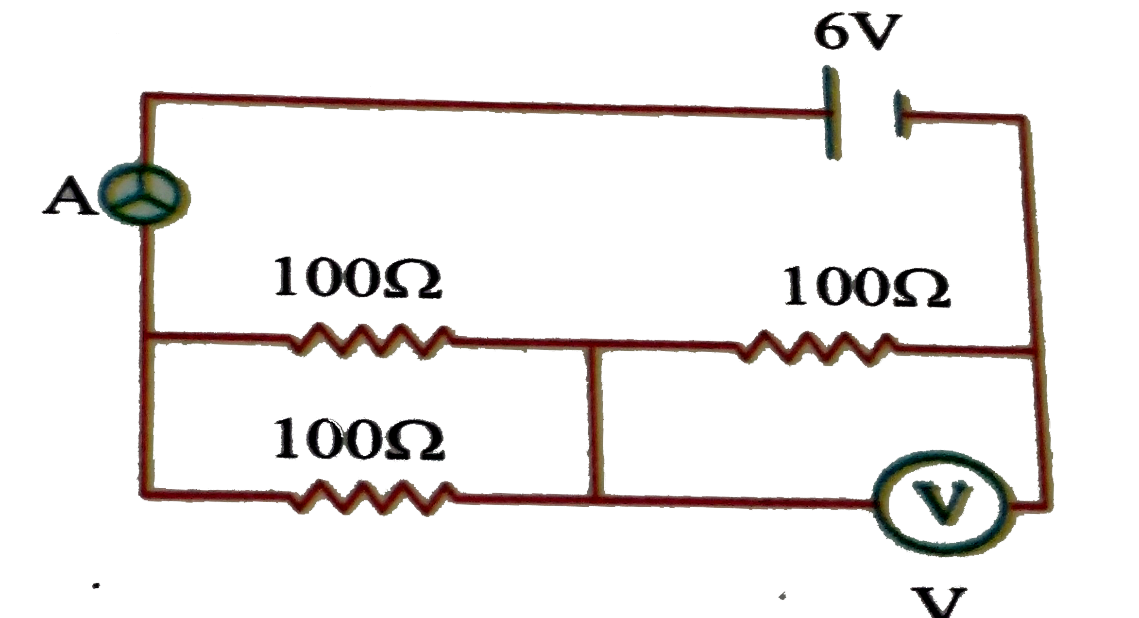
In the circuit shown, the reading of the voltmeter and the ammeter are
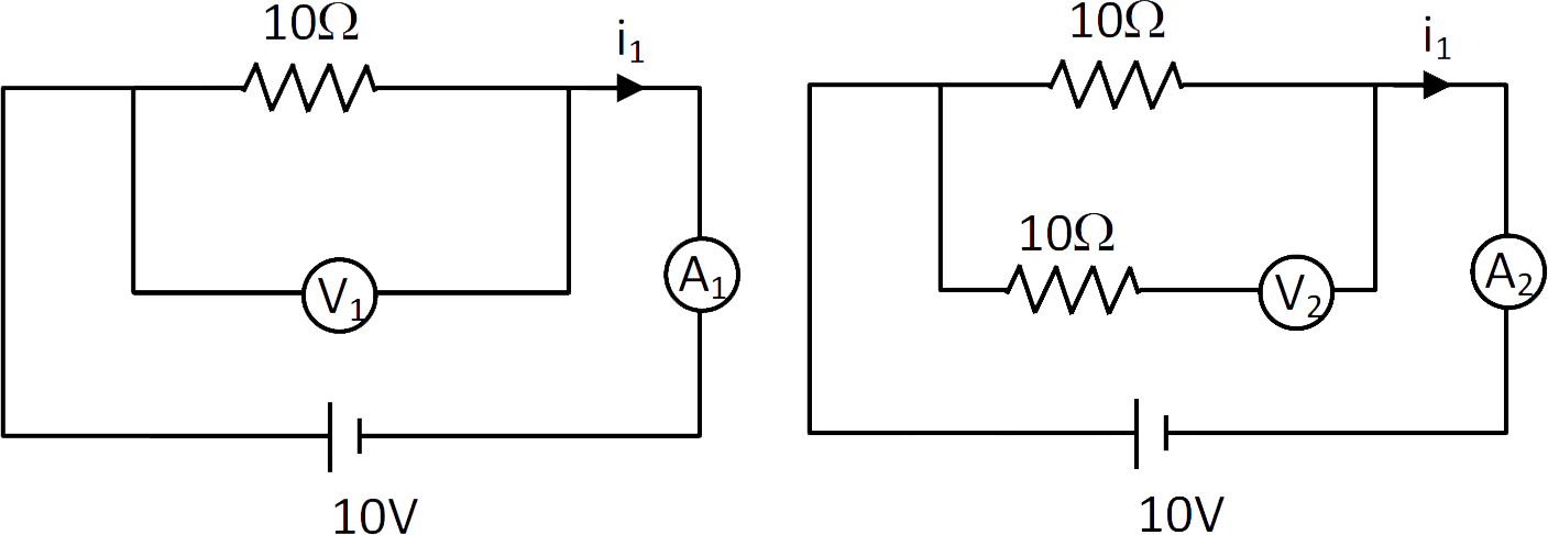
View SolutionIn the circuits shown below, the readings of the voltmeters and the ammeters will be:
View Solution


