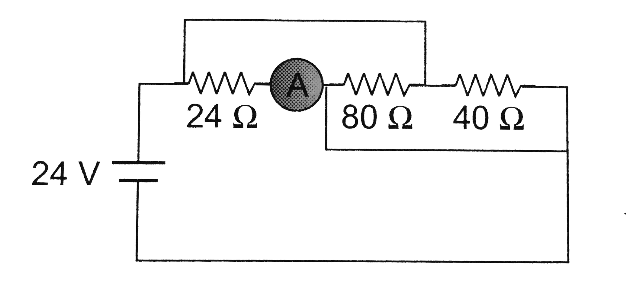
In the circuit shown, the reading of ammeter is:
A
0.2A
B
0.6A
C
2A
D
1A
Video Solution
Text Solution
The correct Answer is:D
(d) All three resistors are connected in parallel to a supply voltage of 24 volt. Ammeter is connected in the branch containing 24Ω resistor. Hence, current throuhg 24Ω resistor is correct.
|
Topper's Solved these Questions
- CURRENT ELECTRICITYBOOK - A2ZCHAPTER - CURRENT ELECTRICITYEXERCISE - Section - A
1 Videos
- CURRENT ELECTRICITYBOOK - A2ZCHAPTER - CURRENT ELECTRICITYEXERCISE - Section B - Assertion Reasoning
28 Videos
- CURRENT ELECTRICITYBOOK - A2ZCHAPTER - CURRENT ELECTRICITYEXERCISE - Heating Effect Of Current
40 Videos
- ATOMIC PHYSICSBOOK - A2ZCHAPTER - ATOMIC PHYSICSEXERCISE - Section D - Chapter End Test
30 Videos
- DUAL NATURE OF RADIATION AND MATTERBOOK - A2ZCHAPTER - DUAL NATURE OF RADIATION AND MATTEREXERCISE - Section D - Chapter End Test
30 Videos
Similar Questions
Knowledge Check
In the circuit shown, the reading of the ammeter if diode is not ideal, will be
 A0B15mAC>15mAD<15mA
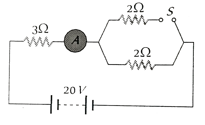
In the circuit shown, the reading of ammeter when switch S is open and when switch S is closed respectively are
 A3A and 4AB4A and 5AC5A and 6AD6A and 7A
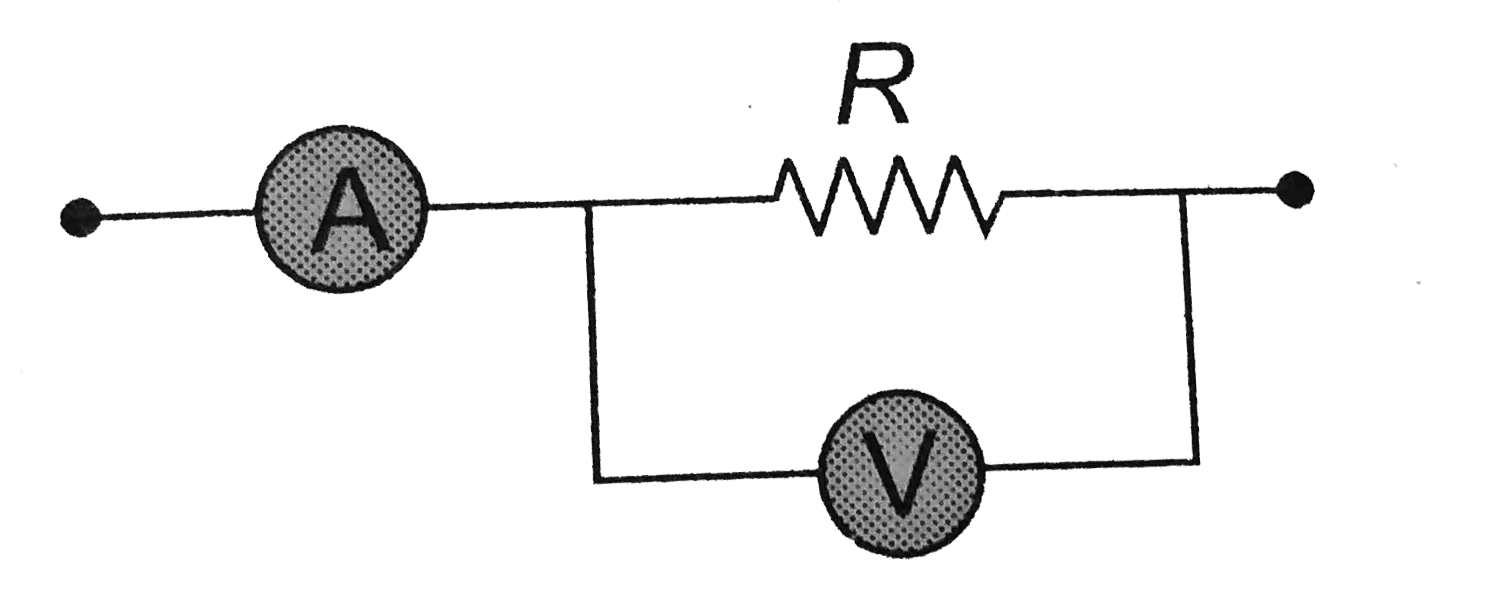
In the circuit shown the reading of ammeter and voltmeter are 4A and 20V respectively. The meters are non ideal, then R ia
 A5ΩBless than 5ΩCgreater than 5ΩDbetween 4Ω and 5Ω
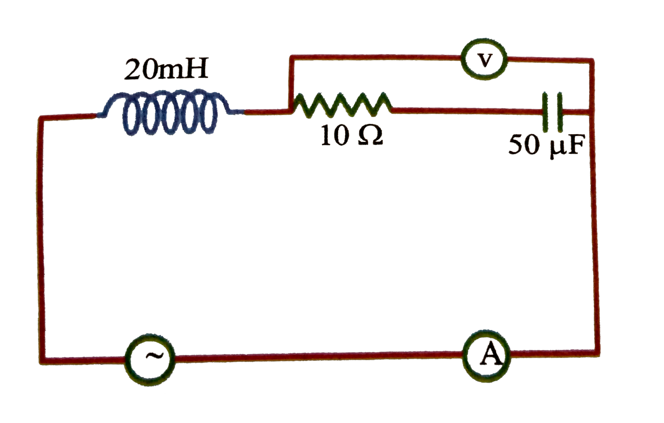
For the AC circuit shown, the reading of ammeter and voltmeter are 5A and 50√5 volts respectively, then
View Solution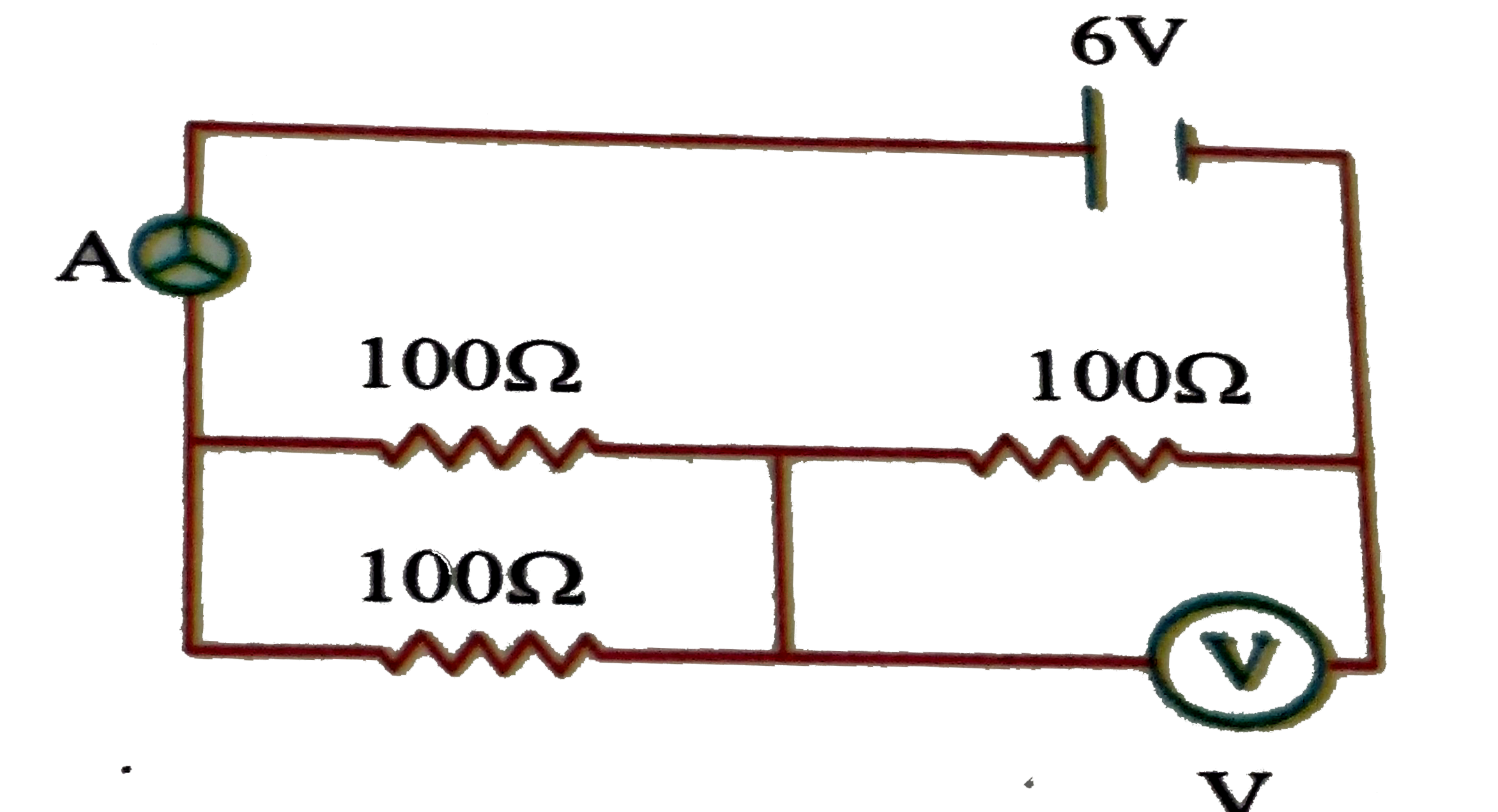
In the circuit shown, the reading of the voltmeter and the ammeter are
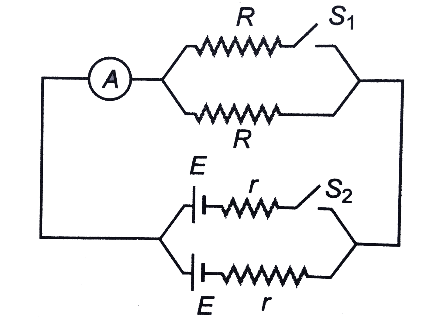
View SolutionIn the circuit shown in figure, reading of ammeter will
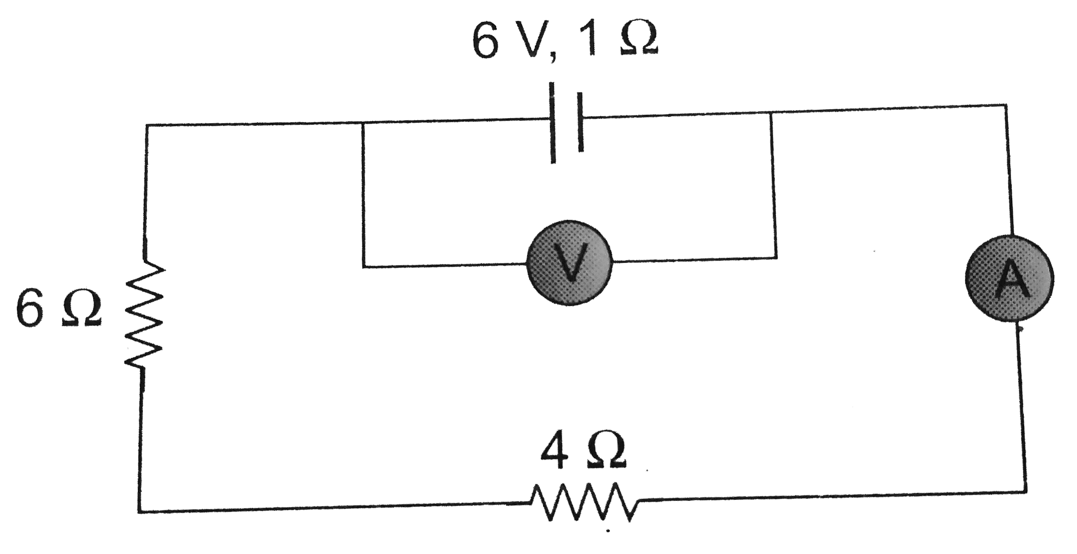
View SolutionIn the circuit shown here, the readings of the ammeter and voltmeter are
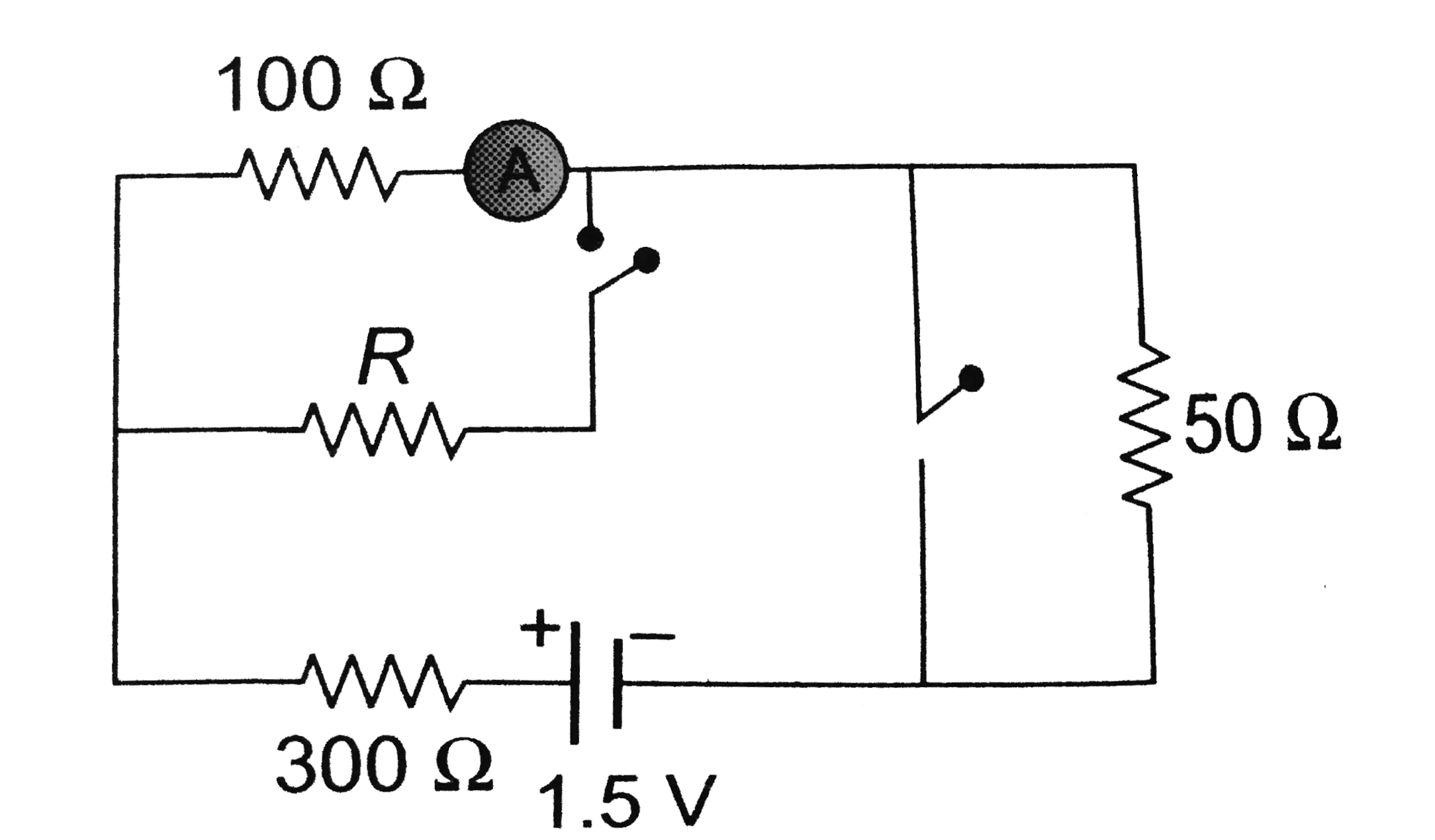
View SolutionIn the circuit shown in figure the reading of ammeter is the same with both switches open as with both closed. Then find the resistance R. (ammeter is ideal).
View Solution

