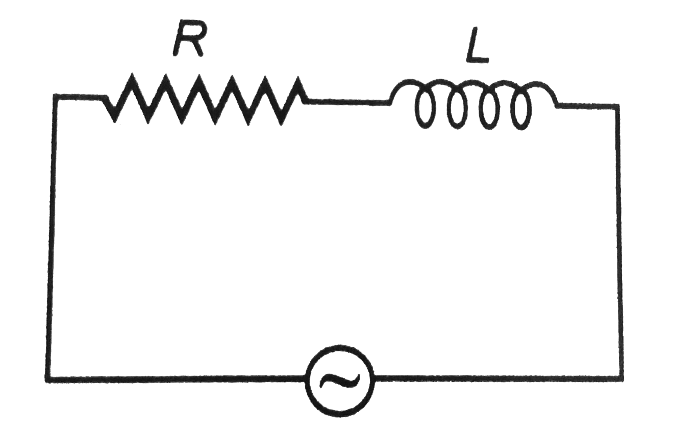
In the circuit shown in figureure, the power consumed is
 .
.
zero
V202R
V20R2(R2+ω2L2)
none of these
The correct Answer is:C
P=I2maxR=(VrmsZ)2R
=⎡⎢
⎢
⎢⎣(V0/√2)2R2+ω2L2⎤⎥
⎥
⎥⎦R
=V20R2(R2+ω2L2)
Topper's Solved these Questions
- ALTERNATING CURRENTBOOK - DC PANDEYCHAPTER - ALTERNATING CURRENTEXERCISE - Level- 2More Than One Correct
8 Videos
- ALTERNATING CURRENTBOOK - DC PANDEYCHAPTER - ALTERNATING CURRENTEXERCISE - Level 2 Comprehension
6 Videos
- ALTERNATING CURRENTBOOK - DC PANDEYCHAPTER - ALTERNATING CURRENTEXERCISE - Level - 1 Subjective
6 Videos
- ATOMSBOOK - DC PANDEYCHAPTER - ATOMSEXERCISE - MEDICAL ENTRANCES GALLERY
42 Videos
Similar Questions
Knowledge Check
In the circuit shown in figure the AC source gives a voltage V=20cos(2000t). Neglecting source resistance, the voltmeter and and ammeter readings will be
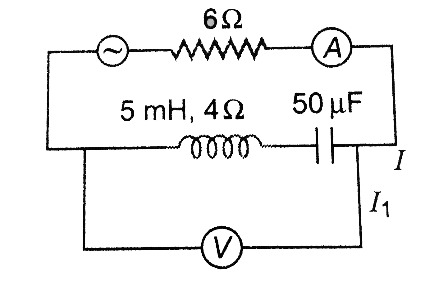 .A0V,2.0AB0V,1.4AC5.6V,1.4AD8V,2.0A
In the circuit shown in figure, power generated in
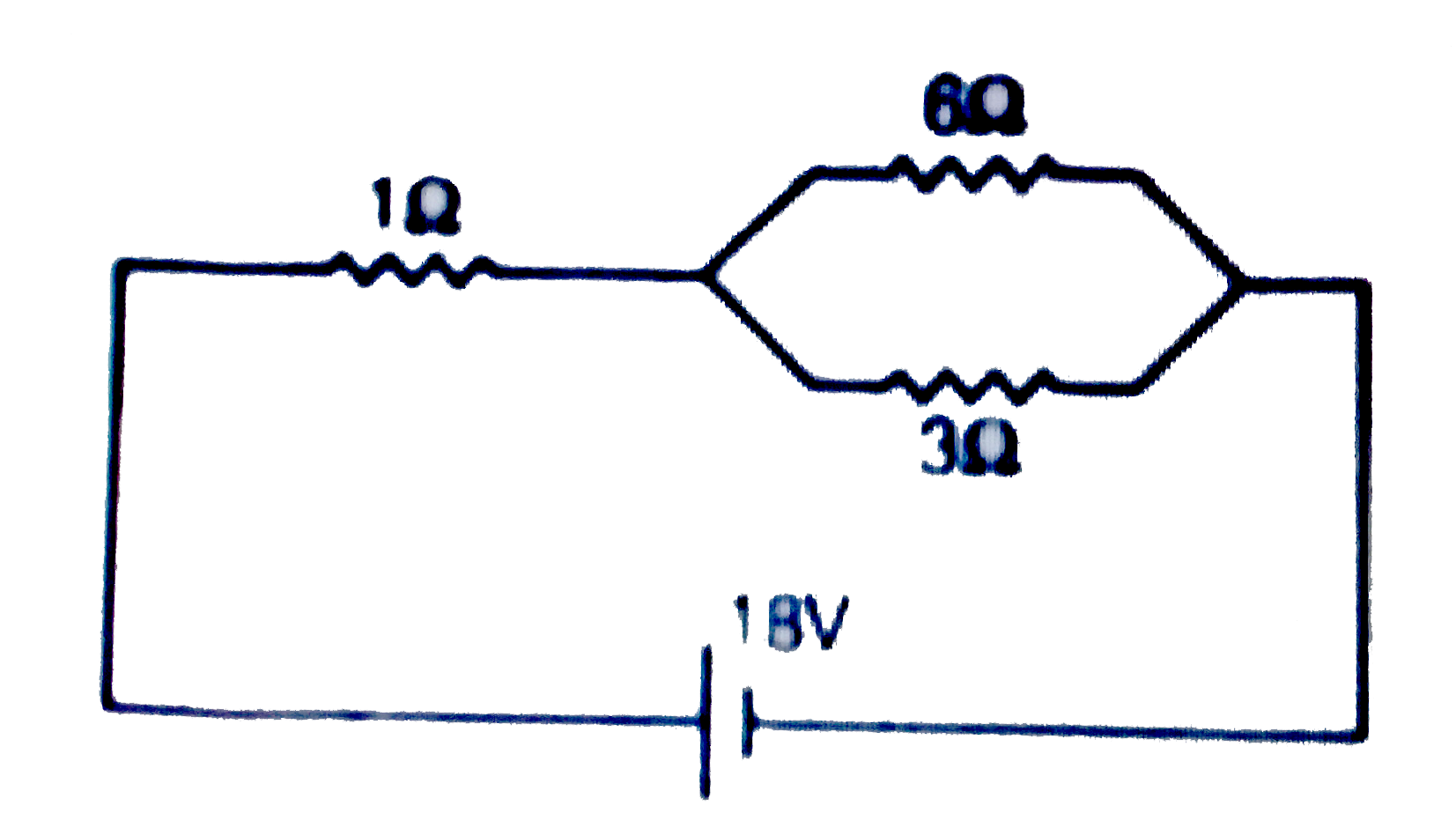 A1Ω resistance is maximumB3Ω resistance is maximumC1Ω resistance is minimumD6Ω resistance is minimum
In the circuit shown in figureure, the reading of the AC ammeter is
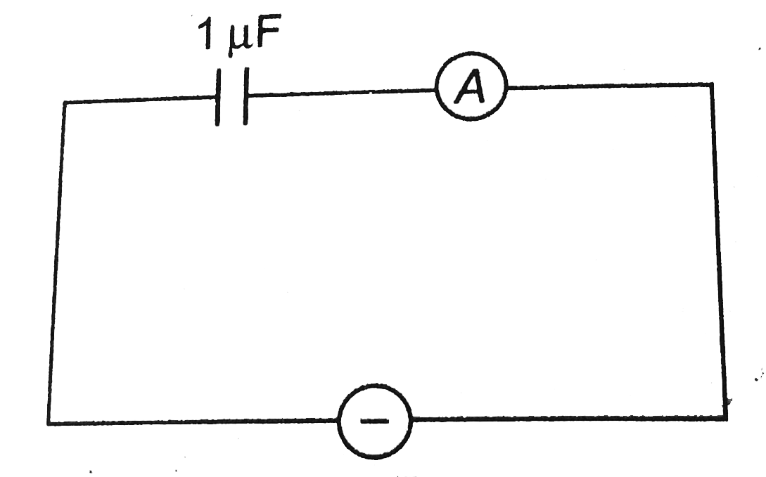 .A20√2mAB40√2mAC20mAD40mA
For the circuit shown in figureure, find the instaneous current through each element.
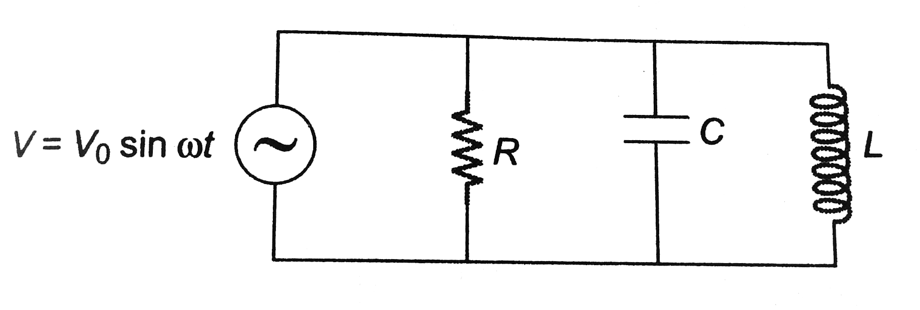 .
.
View SolutionIn a series C−R circuit shown in figureure, the applied voltage is 10V and the voltage across capacitor is found to8V. The voltage across R, and the phase difference between current and the applied voltage will respectively be
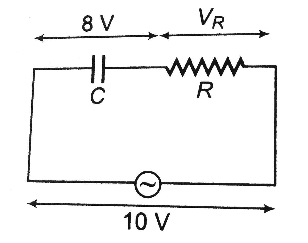 .
.
View SolutionAssertion: In the part of the circuit shown in figure, maximum power is produced across R.
Reason : Power P=V2R
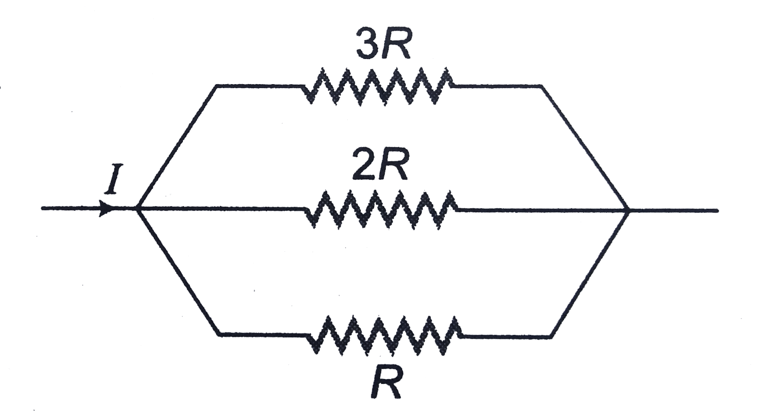
View SolutionThe power dissipated in 3Ω resistor in the circuits as shown in the figure is 2W. The power dissipated in 7Ω resistor will be
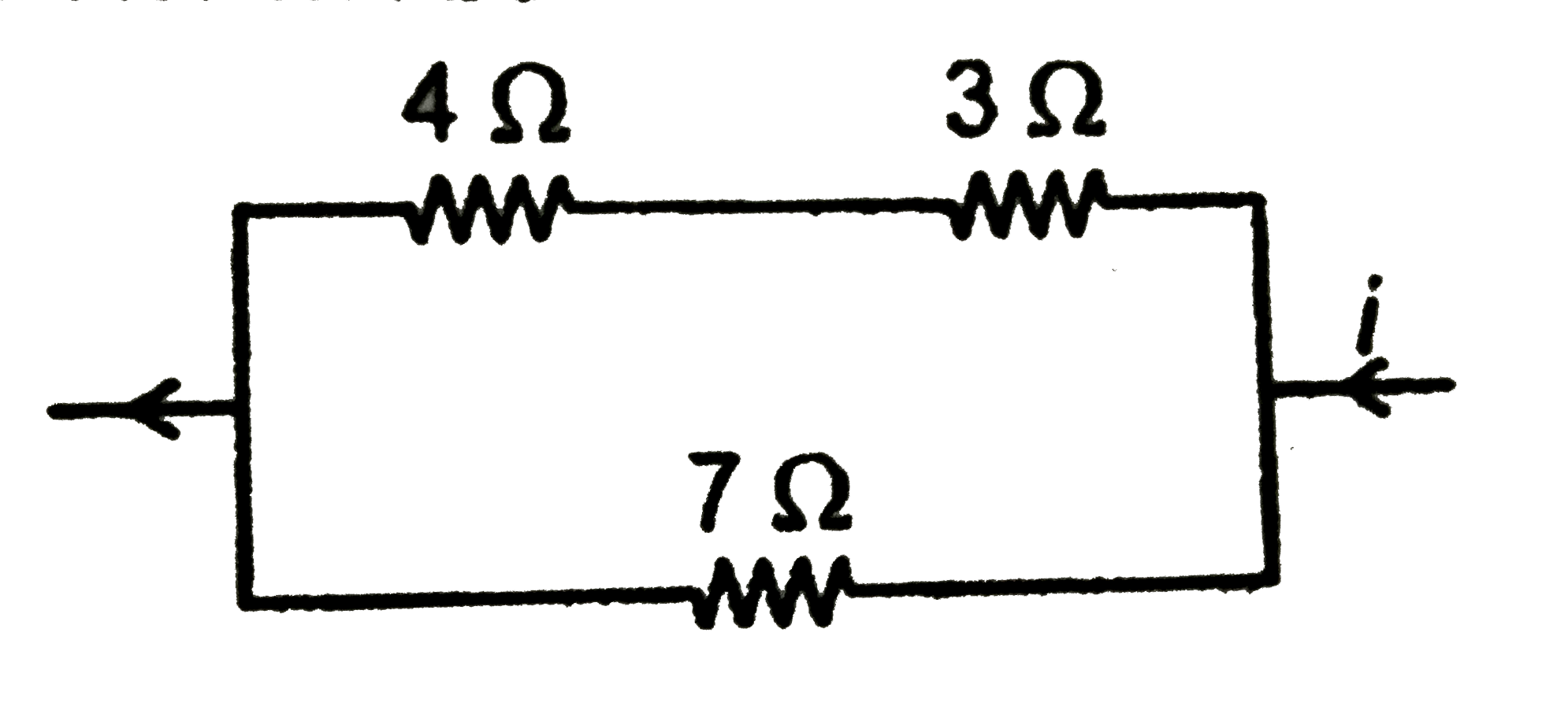
View SolutionA resistor and a capacitor are connected to an ac supply of 200 V, 50 Hz, in series. The current in the circuit is 2A. If the power consumed in the circuit is 100 W then the resistance in the circuit is
View Solution
