A signal generator supplies a sine wave of to the circuit shown in the figure. Then, choose the wrong statement.
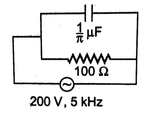 .
.
A
The current in te resistive brance is
B
the current in the capacitive branch is
C
Total line current is
D
Current in both the branches is same
Video Solution
Text Solution
The correct Answer is:B
ahead of the applied voltage and is in phase with the applied voltage. Hence, there is as phase difference of between and too.
.
|
Topper's Solved these Questions
- ALTERNATING CURRENTBook:DC PANDEYChapter:ALTERNATING CURRENTExercise:Level- 2More Than One Correct
Explore 8 Videos
- ALTERNATING CURRENTBook:DC PANDEYChapter:ALTERNATING CURRENTExercise:Level 2 Comprehension
Explore 6 Videos
- ALTERNATING CURRENTBook:DC PANDEYChapter:ALTERNATING CURRENTExercise:Level - 1 Subjective
Explore 6 Videos
- ATOMSBook:DC PANDEYChapter:ATOMSExercise:MEDICAL ENTRANCES GALLERY
Explore 42 Videos
Similar Questions
Knowledge Check
A signal generator supplies a sine wave of 200V,5kHz to the circuit shown in the figure. Then, choose the wrong statement.
 .AThe current in te resistive brance is 0.2ABthe current in the capacitive branch is 0.126ACTotal line current is ≈0.283ADCurrent in both the branches is same
A signal geberatir supplies a sine wave if 20V, 5 to the circuit shown in the figure. Then.
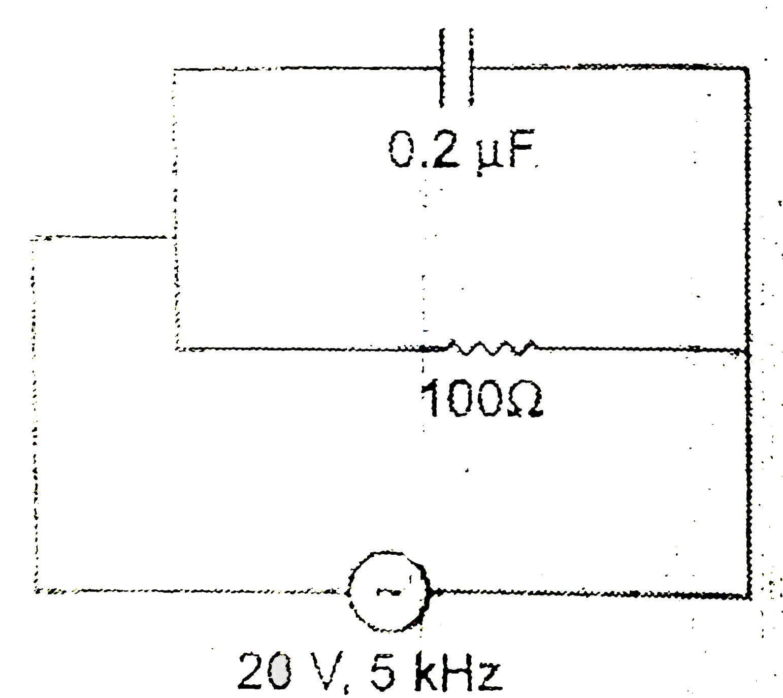 Athe current in the resistive branch is 0.2ABthe current in the capacitive branch is 0.126ACtotal line current is =0.24ADcurrent in both the branches is same
Circuit as shown in figure below, choose the correct statement
 A(A) current in resistance R and current in inductor L.a.c. source will be in 90^(@ phase differenceBotential drop across R and potential drop across L will be in same phaseCcurrent through C and current through L will be in 90∘ phase differenceDcurrent in R and current in L will be in same phase
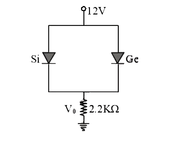
In the circuit shown in figure, Voltage V0 is–
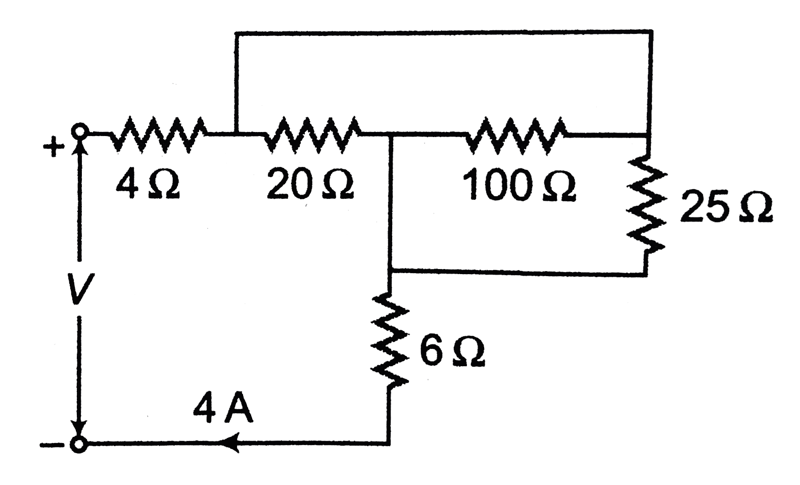
View SolutionIn the circuit shown in figure , V must be
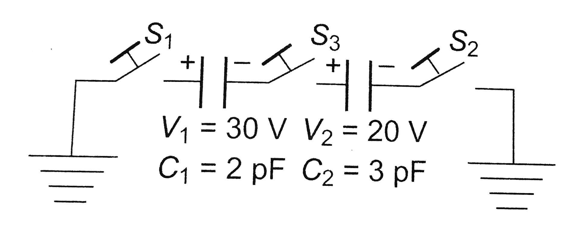
View SolutionFor the circuit shown in figure, which of the following statements is true ?
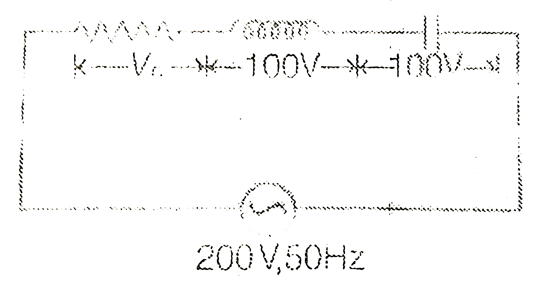
View SolutionIn the circuit shown in figure value of VR is
View SolutionIn the circuit shown in figure, power generated in
View Solution


