Complete Solutions to Grouping Of Capacitors of chapter ELECTRIC POTENTIAL & CAPACITANCE of Class 12 book with complete answers and questions
| Class 12 | PHYSICS |
| Chapter | ELECTRIC POTENTIAL & CAPACITANCE |
| A2Z | Grouping Of Capacitors |
| Number Of Questions | 48 |
| Academic Year | 2023-24 |
Two identical capacitors are joined in parallel, charged to a potential `V` and then separated and then connected in series i.e. the positive plate of one is connected to negative of the other
04:08View SolutionA parallel plate capacitor is made by stacking n equally spaced plates connected alternatively. If the capacitance between any two adjacent plates is 'C' then the resultant capacitance is
05:49View SolutionThe capacitor of capacitance `4 muF` and `6 muF` are connected in series. A potential difference of `500` volts applied to the outer plates of the two capacitor system. Then the charge on each capacitor is numerically
02:52View Solution`n` identical condenser are joined in parallel and are charged to potential `V`. Now they are separated and joined in series. Then the total energy and potential difference of the combination will be
02:38View SolutionThree capacitors of capacitances `3 muF, 9muF` and `18 muF` are connected one in series and another time in parallel. The ratio of equivalent capacitance in the two cases `((C_(s))/(C_(p)))` will be
01:53View SolutionTwo condensers of capacity `0.3 muF` and `0.6muF` respectively are connected in series. The combination is connected across a potential of `6` volts. The ratio of energies stored by the condensers will be
01:51View SolutionTwo capacitances of capacity `C_(1)`and `C_(2)` are connected in series and potential difference `V` is applied across it. Then the potential difference across `C_(1)` will be
02:11View SolutionTwo capacitors connected in parallel having the capacities `C_(1)` and `C_(2)` are given 'q' charge, which is distributed among them. The ratio of the charge on `C_(1)` and `C_(2)` will be
01:36View SolutionThe capacities of two conductors are `C_(1)` and `C_(2)` and their respectively potentials are `V_(1)` and `V_(2)`. If they are connected by a thin wire, then the loss of energy will be given by
03:06View SolutionTwo condenser of capacities `1 muF` and `2 muF` are connected in series and the system is charged to `10` volts. Then the `P.D.` on `1 muF` capacitor (in volts) will be
02:18View SolutionThree identical capacitors are combined differently. For the same voltage to each combination, the one that stores the greatest energy is
02:01View SolutionA condenser having a capacity of `6 muF` is charged to `100 V` and is then joined to an uncharged condenser of `14 muF` and then removed. The ratio of the charges on `6 muF` and `14 muF` and the potential of `6 muF` will be
03:42View Solution`0.2 F` capacitor is charged to `600 V` by a battery. On removing the battery it is connected with another parallel plate condenser of `1 F`. The potential decreases to
03:17View SolutionA condenser of capacitance `10 muF` has been charged to `100V`. It is now connected to another uncharged condenser in parallel. The common potential becomes `40 V`. The capacitance of another condenser is
02:37View SolutionA capacitor `4 muF` charged to `50 V` is connected to another capacitor of `2 muF` charged to `100 V` with plates of like charges connected together. The total energy before and after connection in multiples of `(10^(-2) J)` is
04:14View SolutionTwo capacitors of `3 pF` and `6pF` are connected in series and a potential difference of `5000 V` is applied across the combination. They are then disconnected and reconnected in parallel. The potential between the plates is
03:45View SolutionA condenser of capacity `C_(1)` is charged to a potential `V_(0)`. The electrostatic energy stored in it is `U_(0)`. It is connected to another uncharged condenser of capacity `C_(2)` in parallel. The energy dissipated in the process is
03:46View Solution`100` capacitors each having a capacity of `10 muF` are connected in parallel and are charged by a potential difference of `100 kV`. The energy stored in the capacitors and the cost of charging them, if electrical energy costs `108` paise per `kWh`, will be
03:36View SolutionThree capacitors of `2.0, 3.0` and `6.0 muF` are connected in series to a `10 V` source. The charge on the `3.0 muF` capacitor is
03:09View SolutionA `10 muC` capacitor and a `20 muF` capacitor are connected in series across a `200 V` supply line. The chraged capacitors are then disconnected from the line and reconnected with their positive plates together and negative plates together and no external voltage is applied. what is the potential difference across each capacitor ?
04:40View SolutionTwo condensers `C_(1)` and `C_(2)` in a circuit are joined as shown in figure. The potential of point `A` is ` V_1` and that of `B` is ` V_2` . The potential of point `D` will be `
 00:39View Solution
A `10 muF` capacitor is charged to a potential difference of `50 V` and is connected to another uncharged capacitor in parallel. Now the common potential difference becomes `20` volt. The capacitance of second capacitor is
02:35View SolutionThe combined capacity of the parallel combination of two capacitors is four times their combined capacity when connected in series. This means that
02:28View SolutionA capacitor of `20 muF` is charged to `500` volts and connected in parallel ith another capacitor of `10 muF` and charged to `200` volts. The common potential is
03:34View SolutionThe equivalent capacitance of three capacitors of capacitance `C_(1):C_(2)` and `C_(3)` are connected in parallel is `12` units and product `C_(1).C_(2).C_(3) = 48`. When the capacitors `C_(1)` and `C_(2)` are connected in parallel, the equivalent capacitance is `6` units. then the capacitance are
02:51View SolutionA potential difference of `300` volts is applied to a combination of `2.0 muF` and `8.0 muF` capacitors connected in series. The charge on the `2.0 muF` capacitor is
02:15View SolutionTwo capacitors of `10muF` and `20 muF` are connected in series with a `30 V` battery. The charge on the capacitors will be, respectively
02:21View SolutionThree capacitors of capacitance `3 muF, 10 muF` and `15 muF` are connected in series to a voltage source of `100 V`. The charge on `15 muF` is
02:52View SolutionA `20F` capacitor is charged to `5V` and isolated. It is then connected in parallel with an uncharged `30 F` capacitor. The decrease in the energy of the system will be
03:33View SolutionThree capacitors of `2 muF, 3 muF` and `6 muF` are joined in series and the combination is charged by means of a `24` volt battery. The potential difference between the plates of the `6 muF` capacitor is
02:25View SolutionTwo capacitors of capacitances `3 muF` and `6 muF` are charged to a potential of `12 V` each. They are now connected to each other, with the positive plate of each joined to the negative plate of the other. The potential difference across each will be
03:19View SolutionTwo identical capacitors, have the same capacitance C. One of them is charged to potential `V_1` and the other `V_2`. The negative ends of the capacitors are connected together. When the positive ends are also connected, the decrease in energy of the combined system is
07:33View SolutionA capacitor of `10 muF` charged up to `250` volts is connected in parallel with another capacitor of `5 muF` charged up to `100` volts. The common potential is
02:12View SolutionWhen two identical capacitors are in series have `3 muF` capacitance and when parallel `12 muF`. What is the capacitance of each capacitor ?
01:56View SolutionThree capacitors of capacitance `3 muF` are connected in a circuit. Then their maximum and minimum capacitances will be
02:14View SolutionA series combination of three capacitors of capacities `1 muF, 2muF` and `8 muF` is connected to a battery of e.m.f. `13 volt`. The potential difference across the plates of `2 muF` capacitor will be
03:04View SolutionTwo capacitors of capacitance `2 muF` and `3 muF` are joined in series. Outer plate first capacitor is at `1000` volt and outer plate of second capacitor is earthed (grounded). Now the potential on inner plate of each capacitor will be
02:43View SolutionThree capacitors of capacitance `1 muF, 2muF` and `3 muF` are connected in series and a potential difference of `11 V` is applied across the combination. Then, the potential difference across the plates of `1 muF` capacitor is
02:50View SolutionA `10 muF` capacitor is charged to a potential difference of `1000 V`. The terminals of the charged capacitor are disconnected from the power supply and connected to the terminals of an uncharged `6 muF` capacitor. What is the final potential difference across each capacitor ?
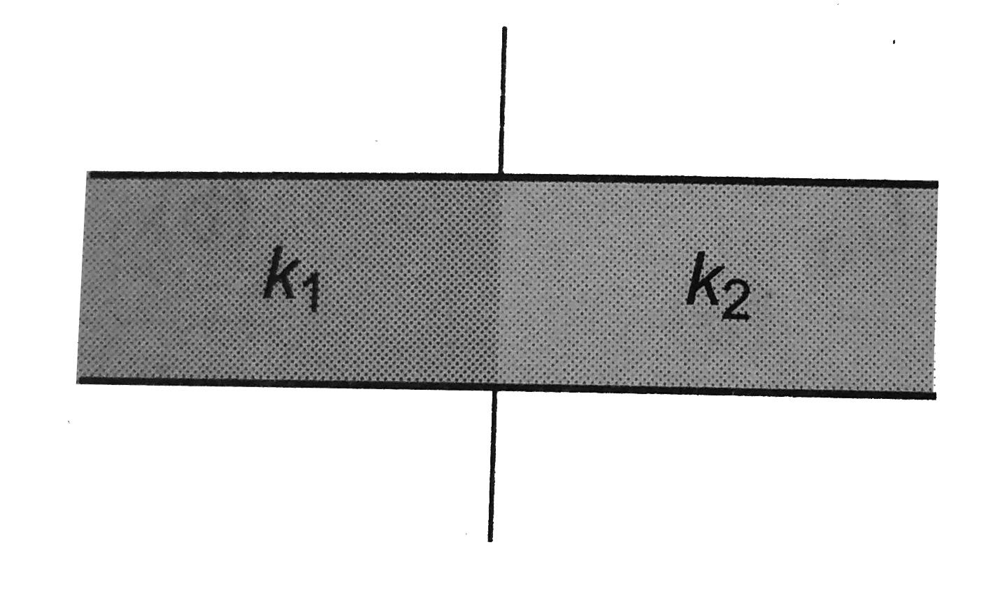
02:29View SolutionA parallel plate capacitor with air as medium between the plates has a capacitance of `10 muF`. The area of capacitor is divided into two equal halves and filled with two media as shown in the figure having dielectric constant `k_(1) = 2` and `k_(2) = 4`. the capacitance of the system will now be
 03:32View Solution
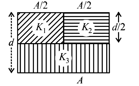
A parallel plate capacitor of area `A`, plate separation d` `and capacitance `C` is filled with three different dielectric materials having dielectric constants `k_1`, `k_2` and `k_3` as shown. If a single dielectric material is to be used to have the same capacitance `C` in this capacitor, then its dielectric constant `k` is given by
 06:03View Solution
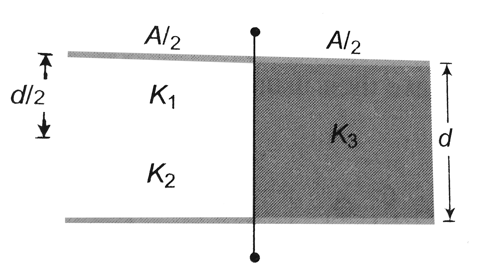
In the figure a capacitor id filled with dielectric. The resultant capacitance is
 03:34View Solution
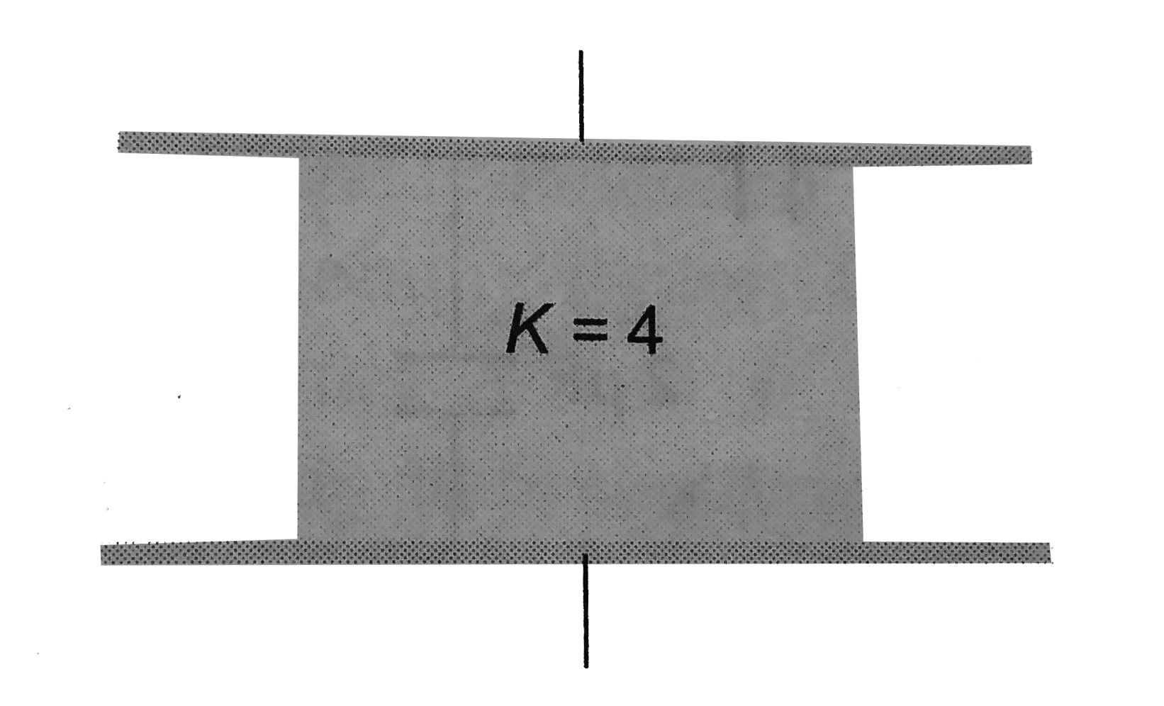
Consider a parallel plate capacitor of `10 muF` with air filled in the gap between the plates. Now one half of the space between the plates is filled with a dielectric of dielectric constant `4`, as shown in the figure. The capacity of the capacitor charges to
 02:54View Solution
A parallel plate capacitor has capacitance `C`. If it is equally filled with parallel layers of materials of dielectric constants `K_(1)` and `K_(2)` its capacity becomes `C_(1)`. The ratio of `C_(1) to C` is
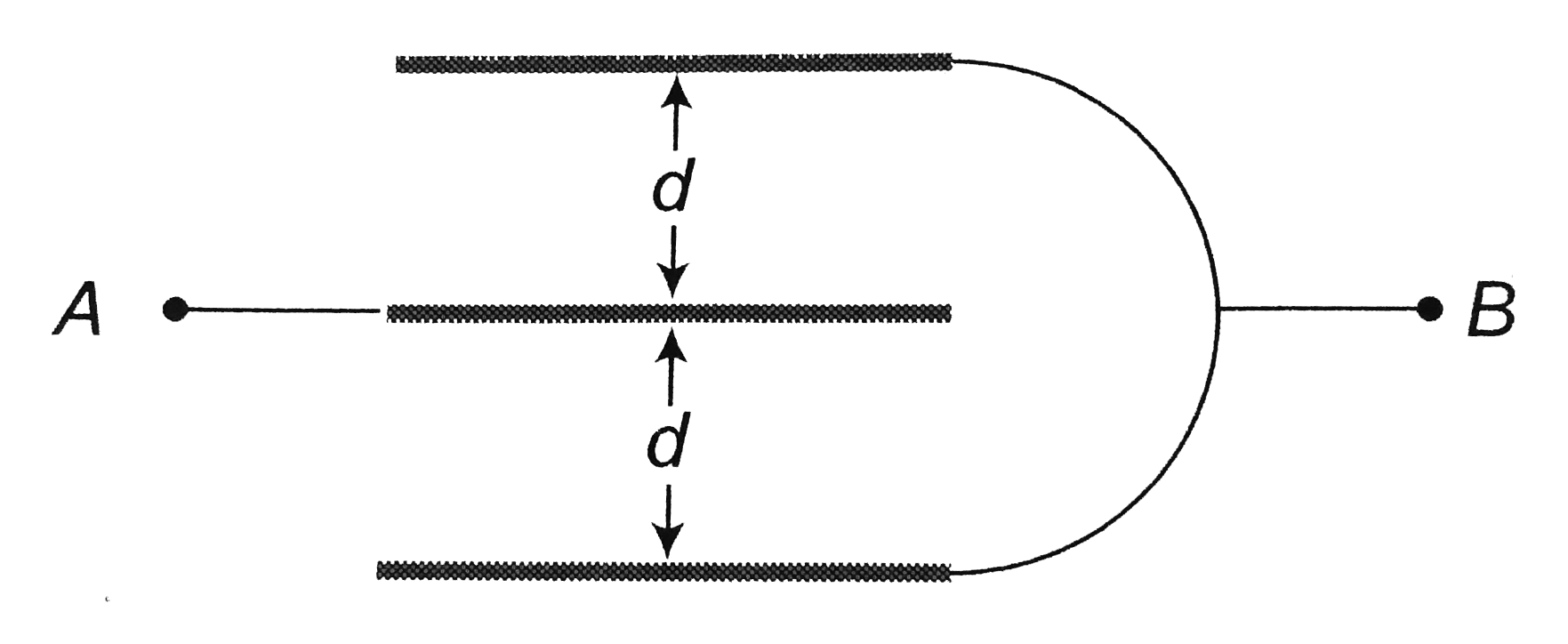
03:03View SolutionThree plates of common surface area `A` are connected as shown. The effective capacitance will be
 02:22View Solution
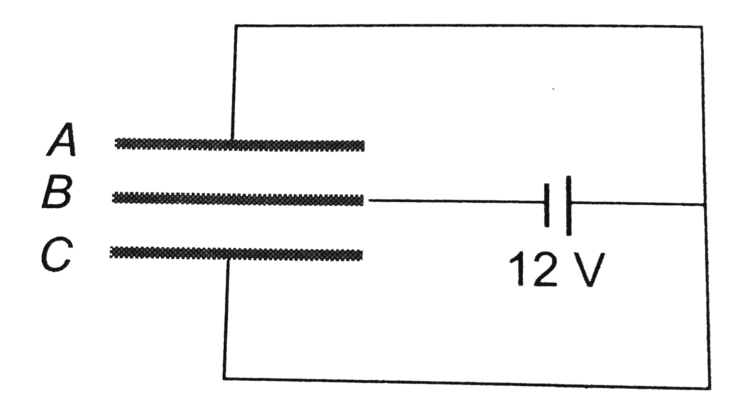
Three plates `A, B, C` each of area `50 cm^(2)` have separation `3 mm` between `A` and `B mm` between `B` and `C`. The energy stored when the plates area fully charged is
 02:36View Solution
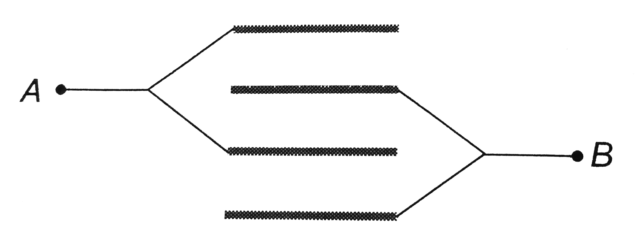
Four plates of the same area of cross-section are joined as shown in the figure. The distance each plate is `d`. The equivalent capacity across `A` and `B` will be
 04:12View Solution
Four plates of equal area `A` are separated by equal distance `d` and are arranged as shown in the figure. The equivalent capacity is
 03:02View Solution
Grouping Of Capacitors questions and complete solutions for chapter ELECTRIC POTENTIAL & CAPACITANCE of A2Z PHYSICS (HINGLISH) of Class 12
All Exercises from A2Z Class 12 PHYSICS ELECTRIC POTENTIAL & CAPACITANCE
- AIIMS Questions
- AIPMTNEET Questions
- Assertion Reason
- Capacitor
- Capacitor Circuits
- Capacitor With Dielectric
- Electric Potential
- Electric Potential Energy
- Euipotentials
- Grouping Of Capacitors
- Problems Based On Mixed Concepts
- Relation Between Electric Field And Potential
- Section B - Assertion Reasoning
- Section D - Chapter End Test
