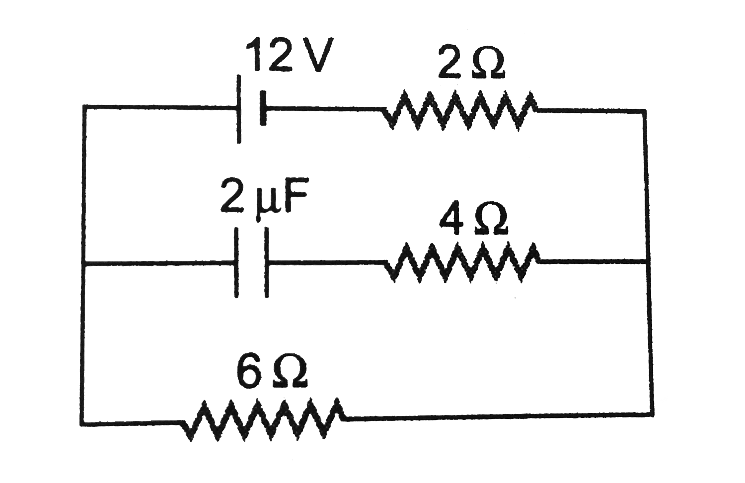
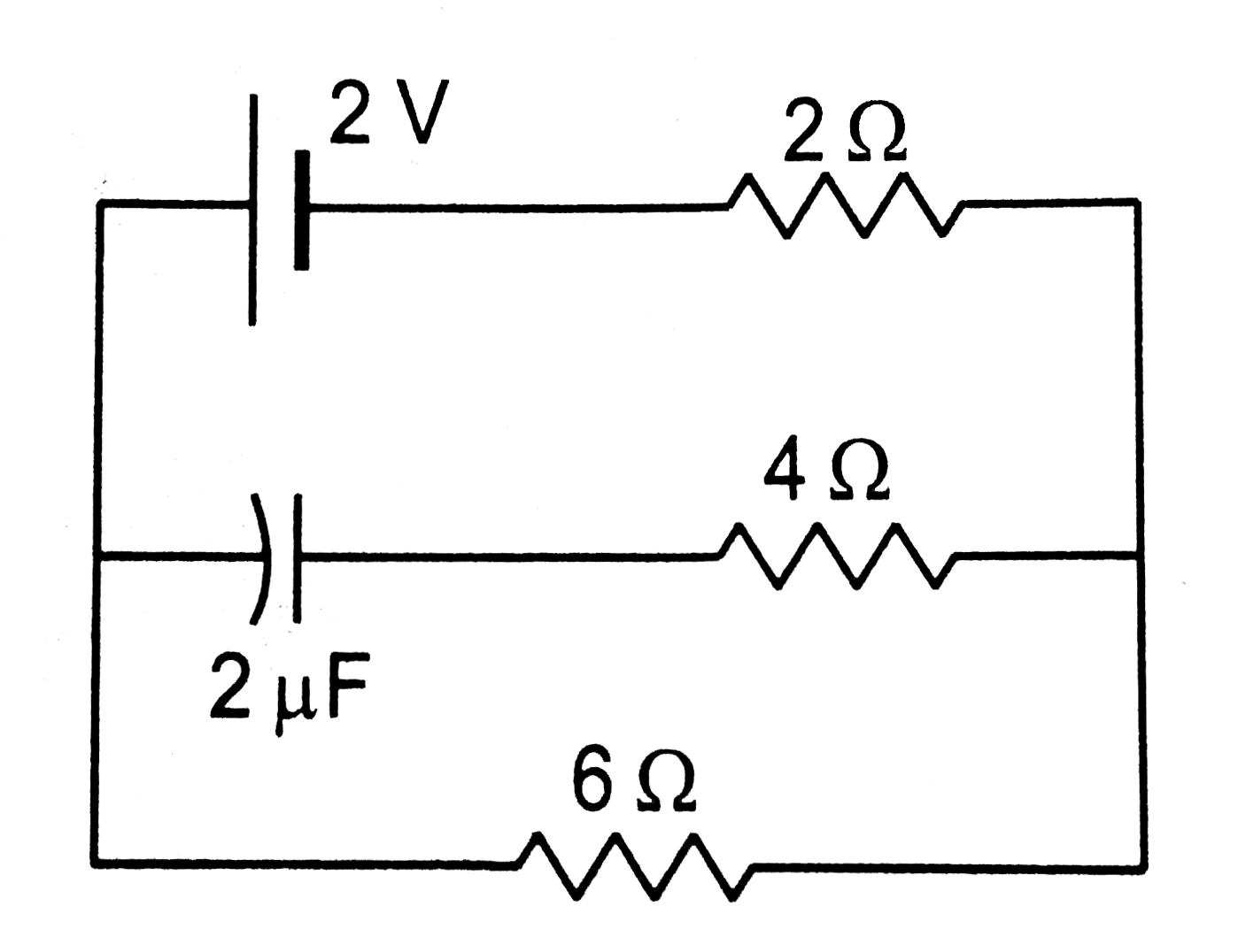
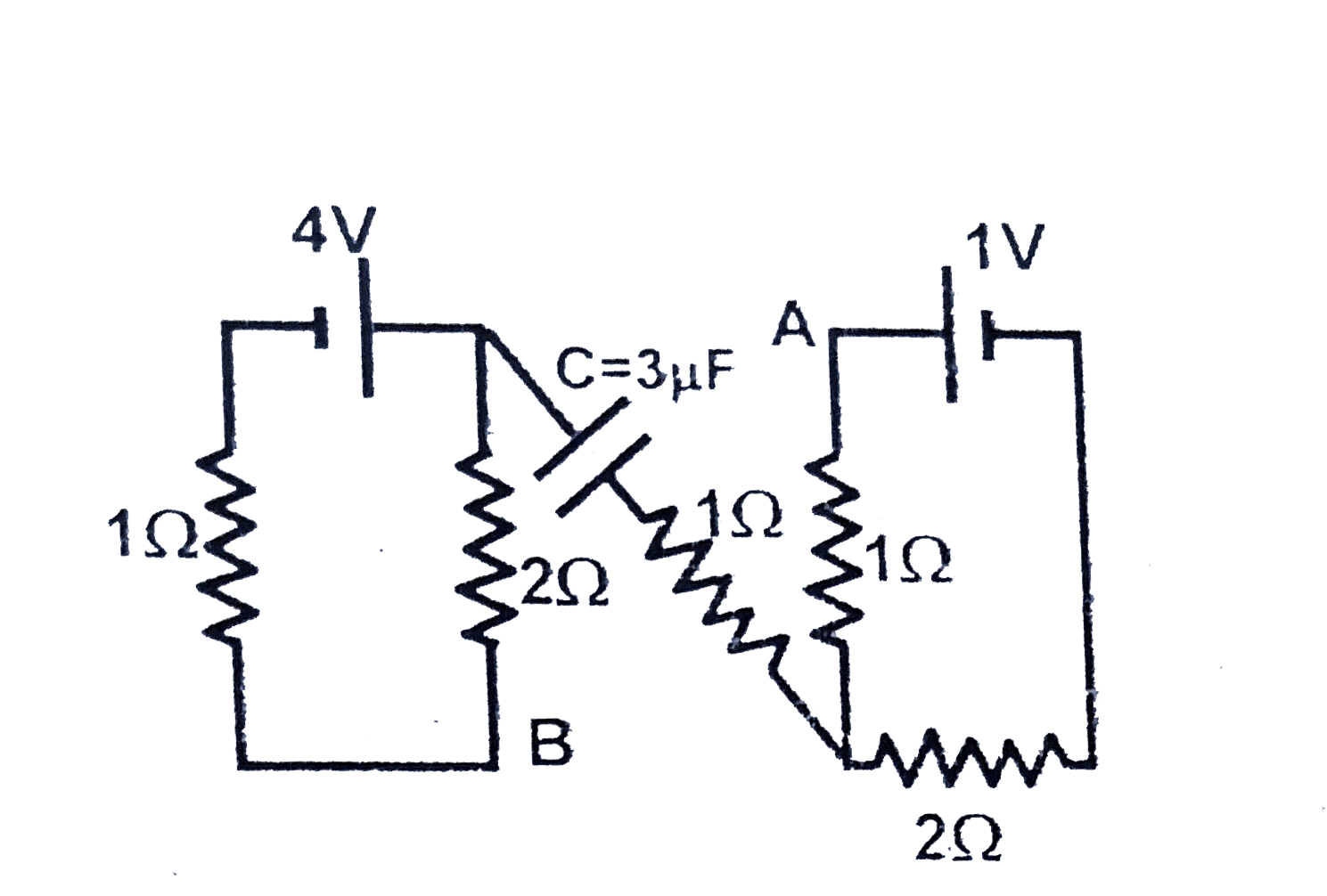
For the circuit arrangement shown in figure, in the steady state condition charge on the capacitor is
12μC
14μC
2μC
18μC
The correct Answer is:D
In steady state condition, current flows from outermost loop.
i=126+2=1.5A
Now, VC=V6Ω=iR
=1.5×6=9V
∴q=CVC=18μC
Topper's Solved these Questions
- CAPACITORSBook:DC PANDEY ENGLISHChapter:CAPACITORSExercise:OBJECTIVE_TYPE
Explore 1 Video
- CAPACITORSBook:DC PANDEY ENGLISHChapter:CAPACITORSExercise:OBJECTIVE_TYPE
Explore 1 Video
- ATOMSBook:DC PANDEY ENGLISHChapter:ATOMSExercise:MEDICAL ENTRANCES GALLERY
Explore 42 Videos
- COMMUNICATION SYSTEMBook:DC PANDEY ENGLISHChapter:COMMUNICATION SYSTEMExercise:Subjective
Explore 11 Videos
Similar Questions
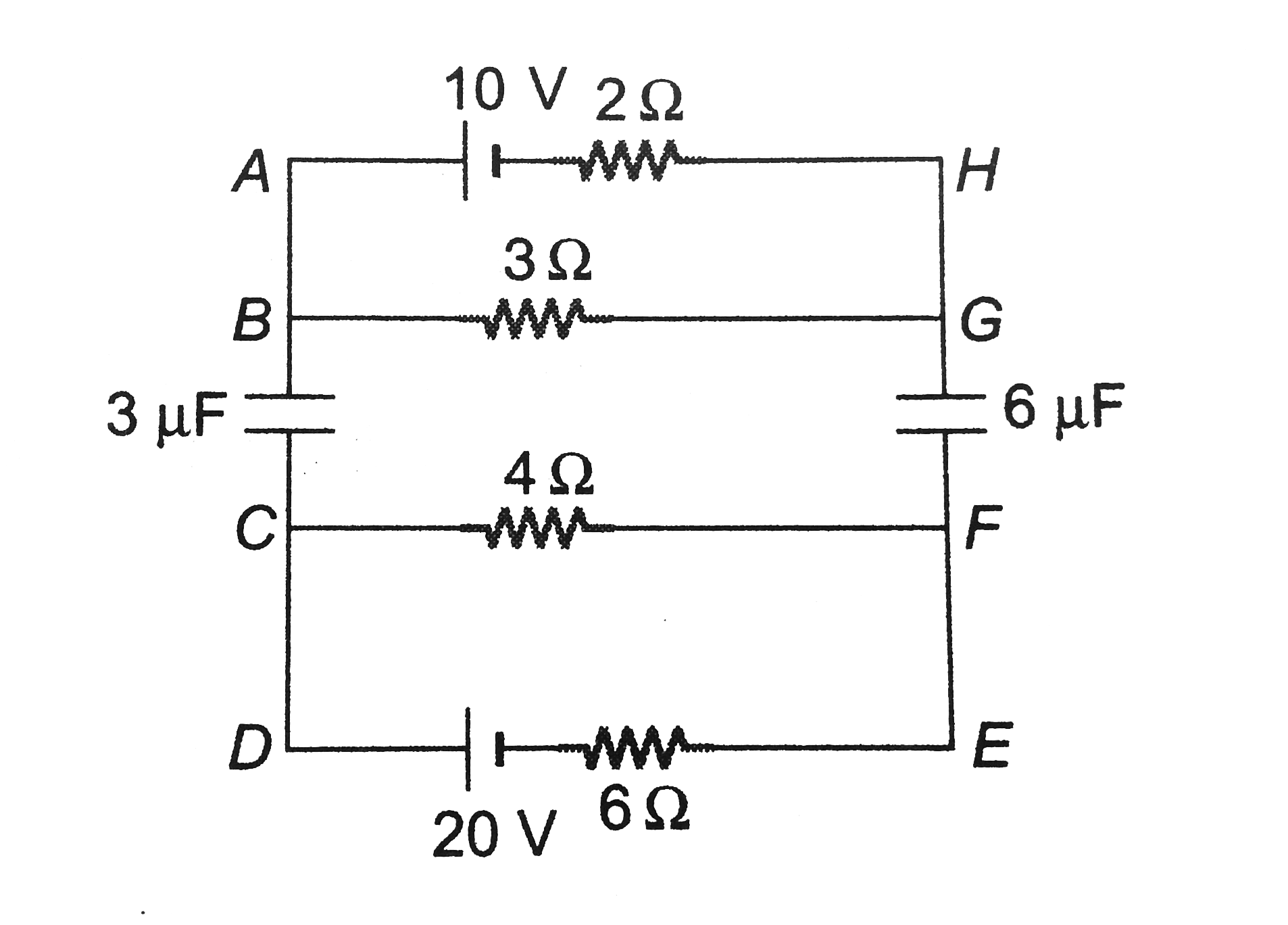
In the circuit shown in figure, find the steady state charges on oth the capacitors.
View SolutionFor the circuit arrangement shown in fig.
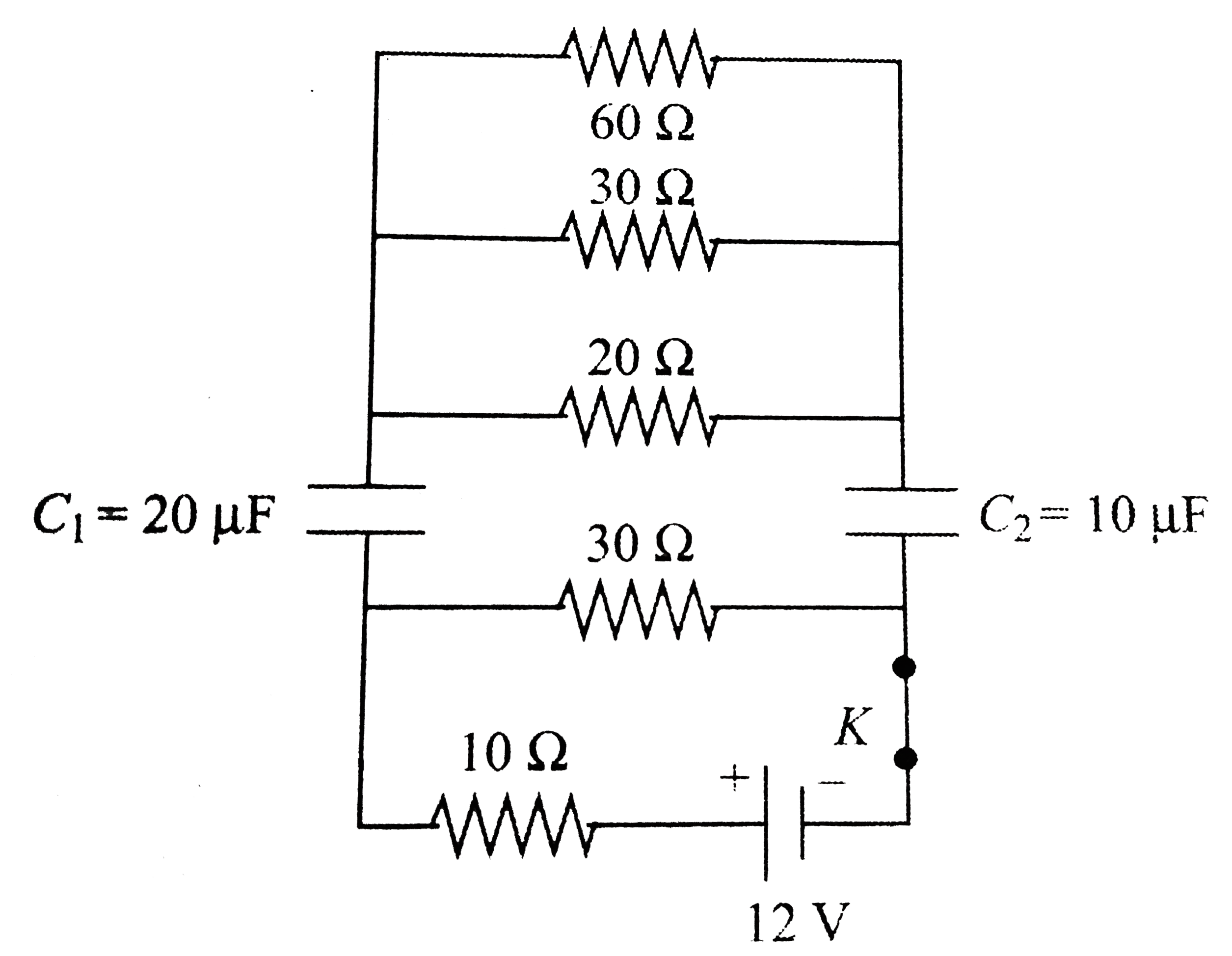
a. Find the potentail difference across each capacitor in the steady - state condition.
b. Find the current through the 60Ω resistor just after the instant when the key K is opened.
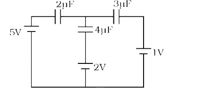
View SolutionIn steady state, find the charge on 3μF capacitor in μC
View SolutionIn the circuit shown in the figure, in steady state:
The charge on 5μF capacitor is
View Solution(a)Find the current I supplied by the battery in the network shown in figure in steady state. (b)find the charge on the capacitor.
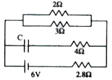
View SolutionIn the steady state, the charge on the capacitor capacity 0.2μF is
View SolutionThe capacitors shown in figure. Is in steady state. The energy stored in the capacitor is

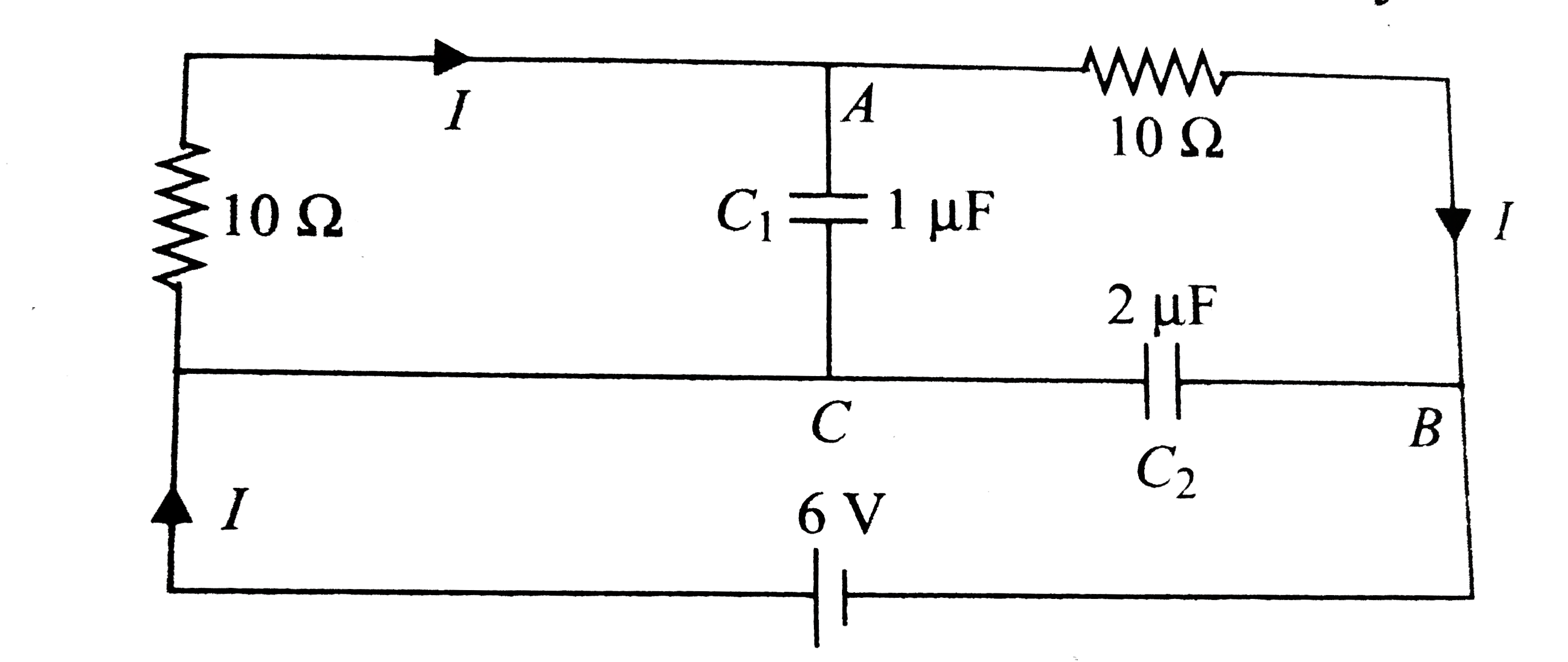
View SolutionThe circuit shown in fig 5.223 is in steady state.
find the charges on the capacitors C1andC2 respectively.
View Solution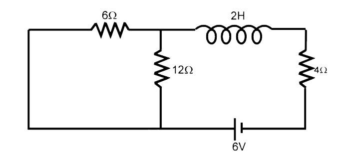
In the circuit shown in figure, time constant and steady state current will be
View SolutionIn the circuit shown in the adjacent figure, the batteries are ideal. The charge on the capacitor C is
View Solution

