For the circuit arrangement shown in fig.
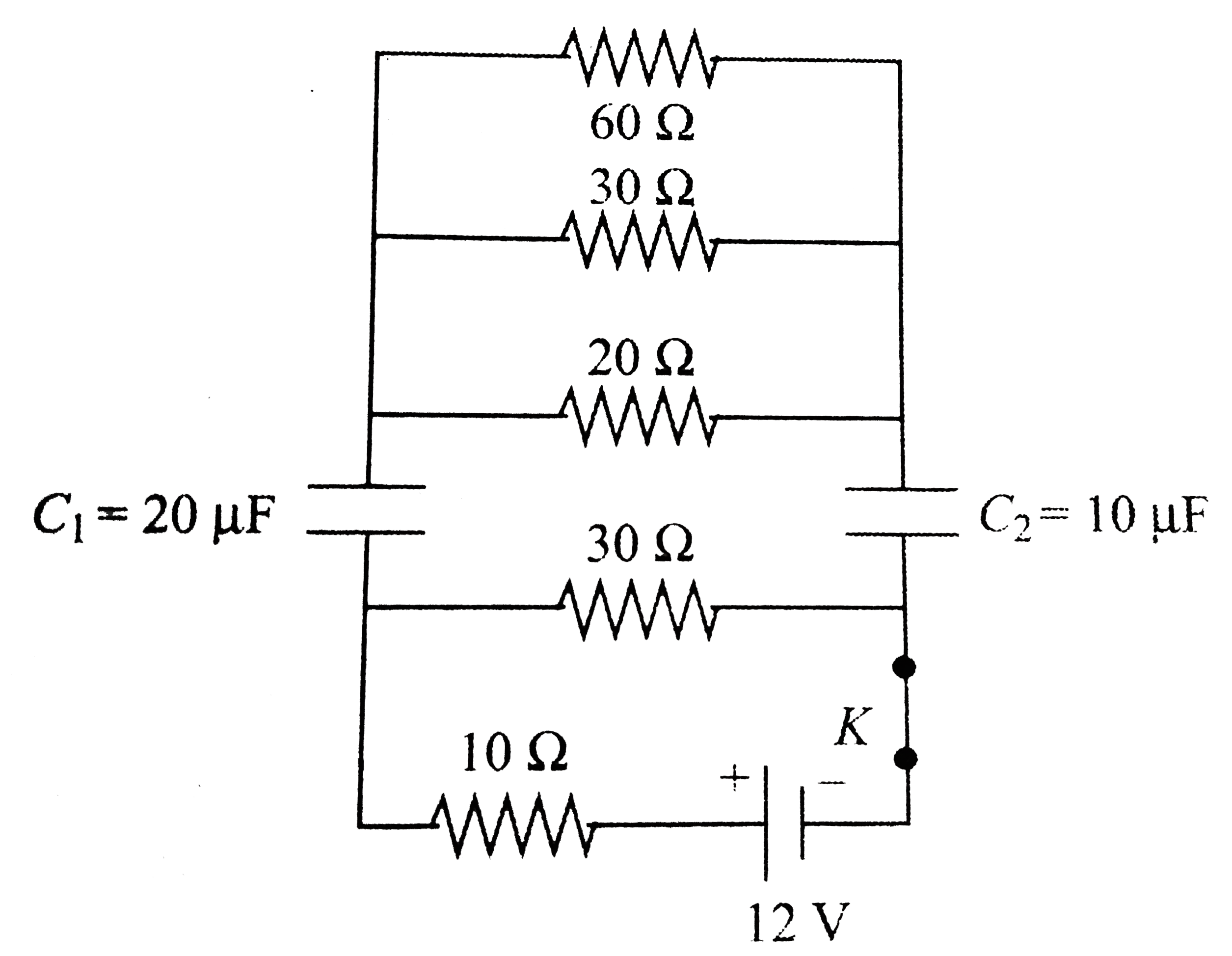
a. Find the potentail difference across each capacitor in the steady - state condition.
b. Find the current through the 60Ω resistor just after the instant when the key K is opened.
In the steady state, no current passes through upper three
resistors. So I=1210+30=0.3A
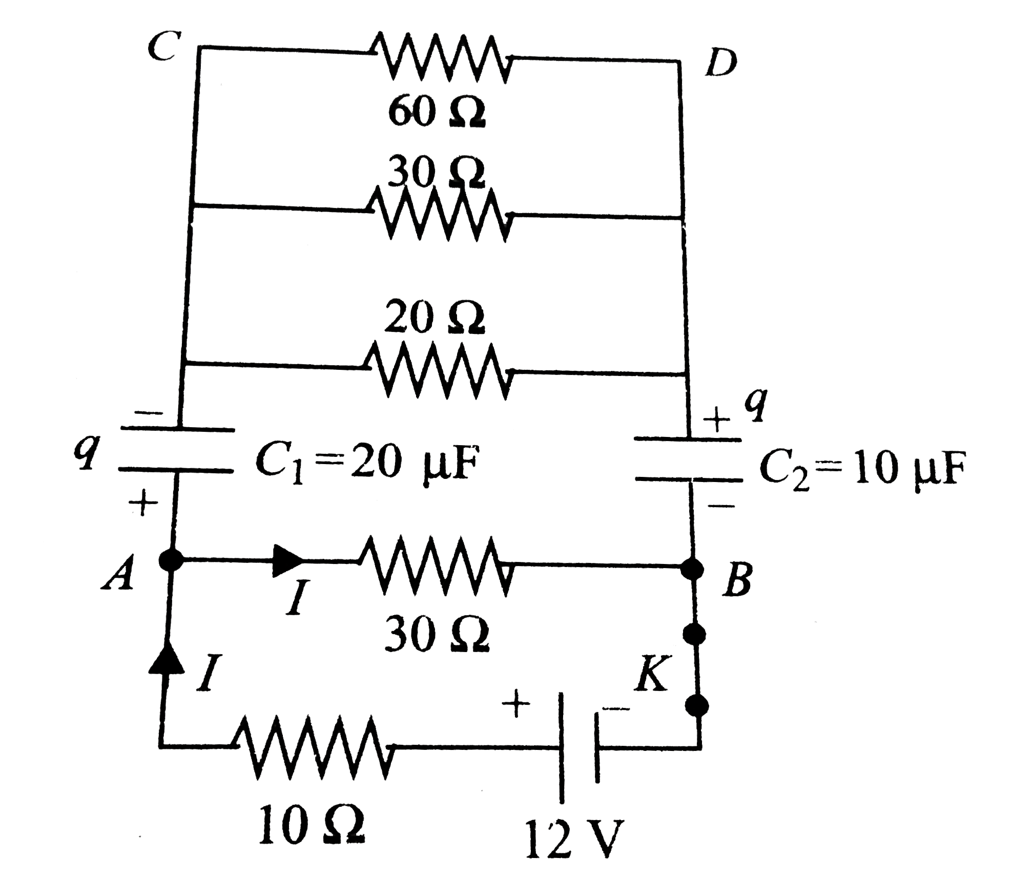
Potential difference between A and B is V=30×0.3=9V.
Now in loop ACDBA:
qC1+qC2=9
or q20+q10=9orq=60μC
a. Potential difference across C1:
V1=qC1=6020=3V
Potential difference across C2:
V2=qC2=6010=6V
b. After K is opened, 12 V will be out of circuit , and capacitors
will act as batteries as shown in fig.

Now one can find I1=0.0375A.
Topper's Solved these Questions
- ELECTRIC CURRENT AND CIRCUITBOOK - CENGAGE PHYSICS ENGLISHCHAPTER - ELECTRIC CURRENT AND CIRCUITEXERCISE - Single Correct
72 Videos
- ELECTRIC CURRENT AND CIRCUITBOOK - CENGAGE PHYSICS ENGLISHCHAPTER - ELECTRIC CURRENT AND CIRCUITEXERCISE - Multiple Correct
16 Videos
- ELECTRIC CURRENT AND CIRCUITBOOK - CENGAGE PHYSICS ENGLISHCHAPTER - ELECTRIC CURRENT AND CIRCUITEXERCISE - Exercise 5.2
50 Videos
- ELECTRIC CURRENT & CIRCUITSBOOK - CENGAGE PHYSICS ENGLISHCHAPTER - ELECTRIC CURRENT & CIRCUITSEXERCISE - Kirchhoff s law and simple circuits
15 Videos
- ELECTRIC FLUX AND GAUSS LAWBOOK - CENGAGE PHYSICS ENGLISHCHAPTER - ELECTRIC FLUX AND GAUSS LAWEXERCISE - MCQ s
38 Videos
Similar Questions
In the circuit diagram shown in find the current through the 1Ω resistor.

View SolutionFind the current through 4Ω resistor in the circuit shown in figure.
View SolutionIn a circuit shown in fig find the potentail difference between the left and right plates of each capacitor.

View SolutionConsider the circuit shown in figure.Find the current through the10(Ω)resistor when the switch S is (a)open (b)closed .
View SolutionRefer to Fig. 7.49.
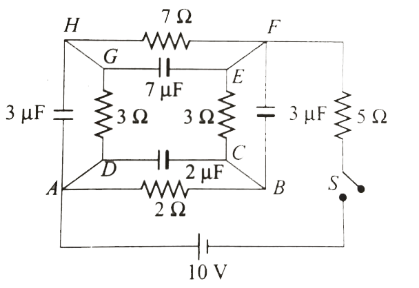
Long time after closing the switch , find the current through the 5Ω resistor.
View SolutionIn the arrangement shown in, When the switch S is closed, find
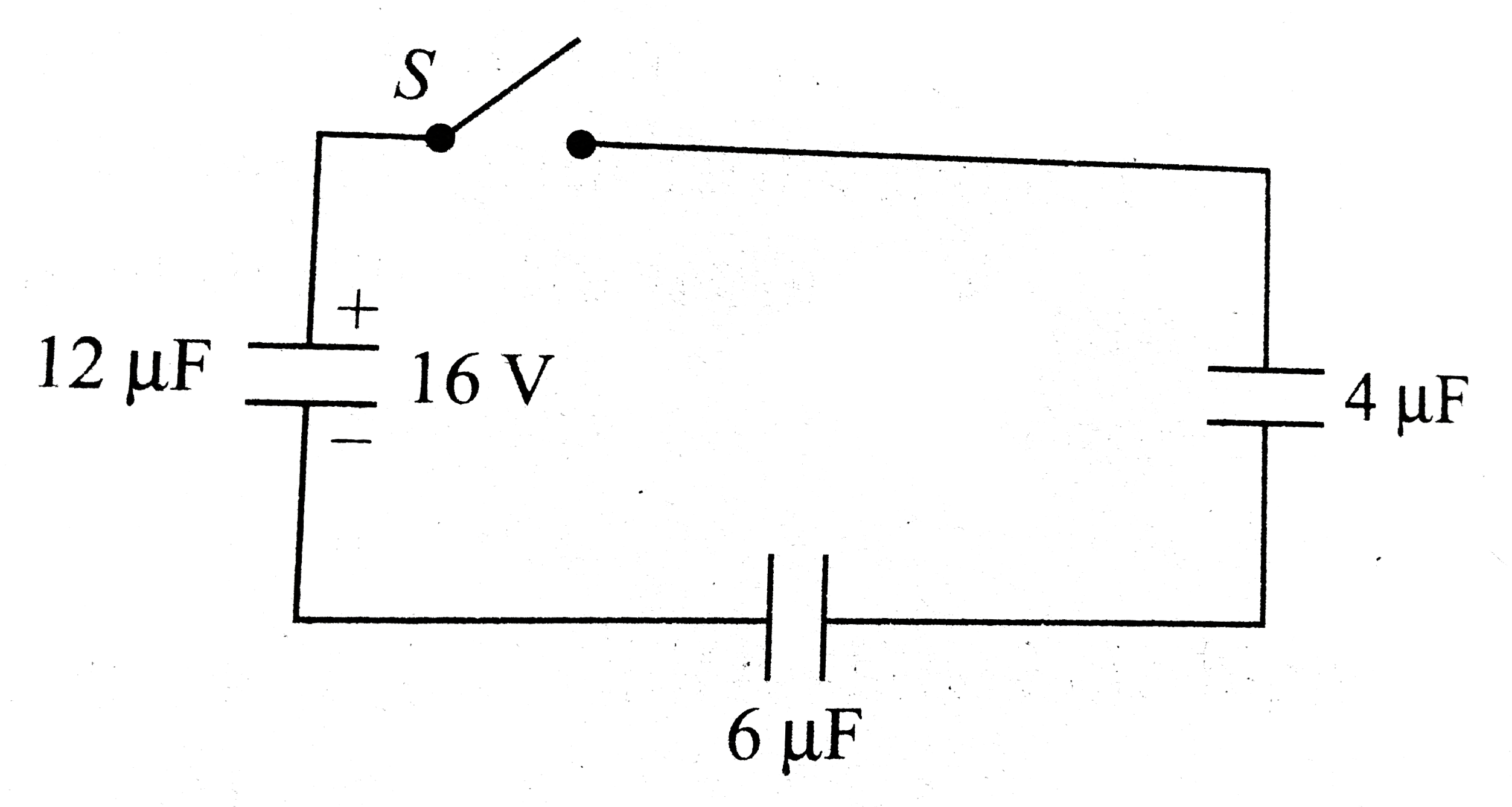 .
.
the final potential difference across the 12μF capacitor.
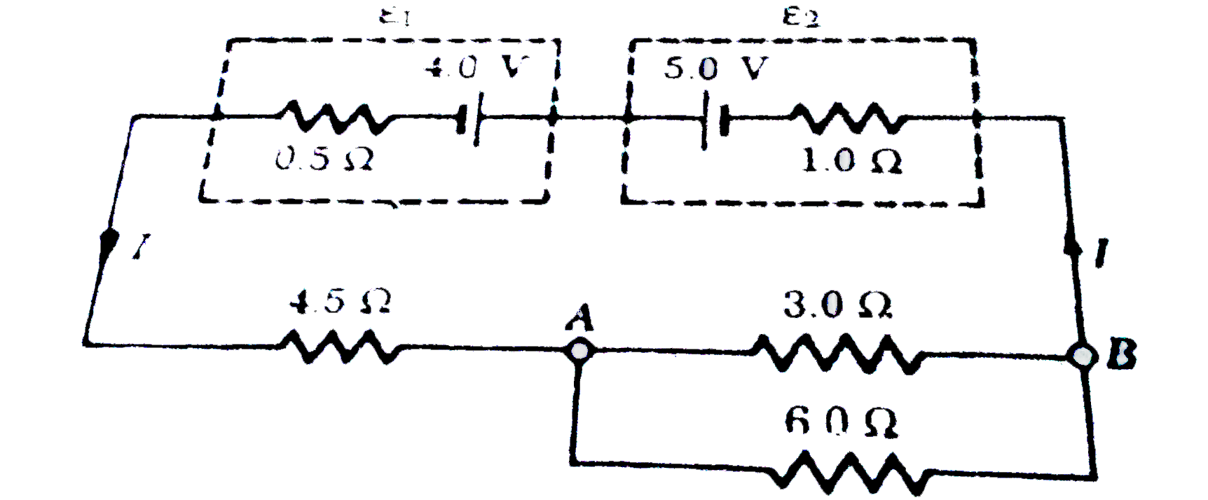
View SolutionIn the circuit shown in Fig. 4.41, calculate the current in each resistor and potential difference across each resistor.
View SolutionThere identical point masses, each of mass 1 kg lie in the xy-plane at points (0, 0), (0, 0.2 m) and (0, 2m, 0). The net gravitational force on the mass at the origin is:
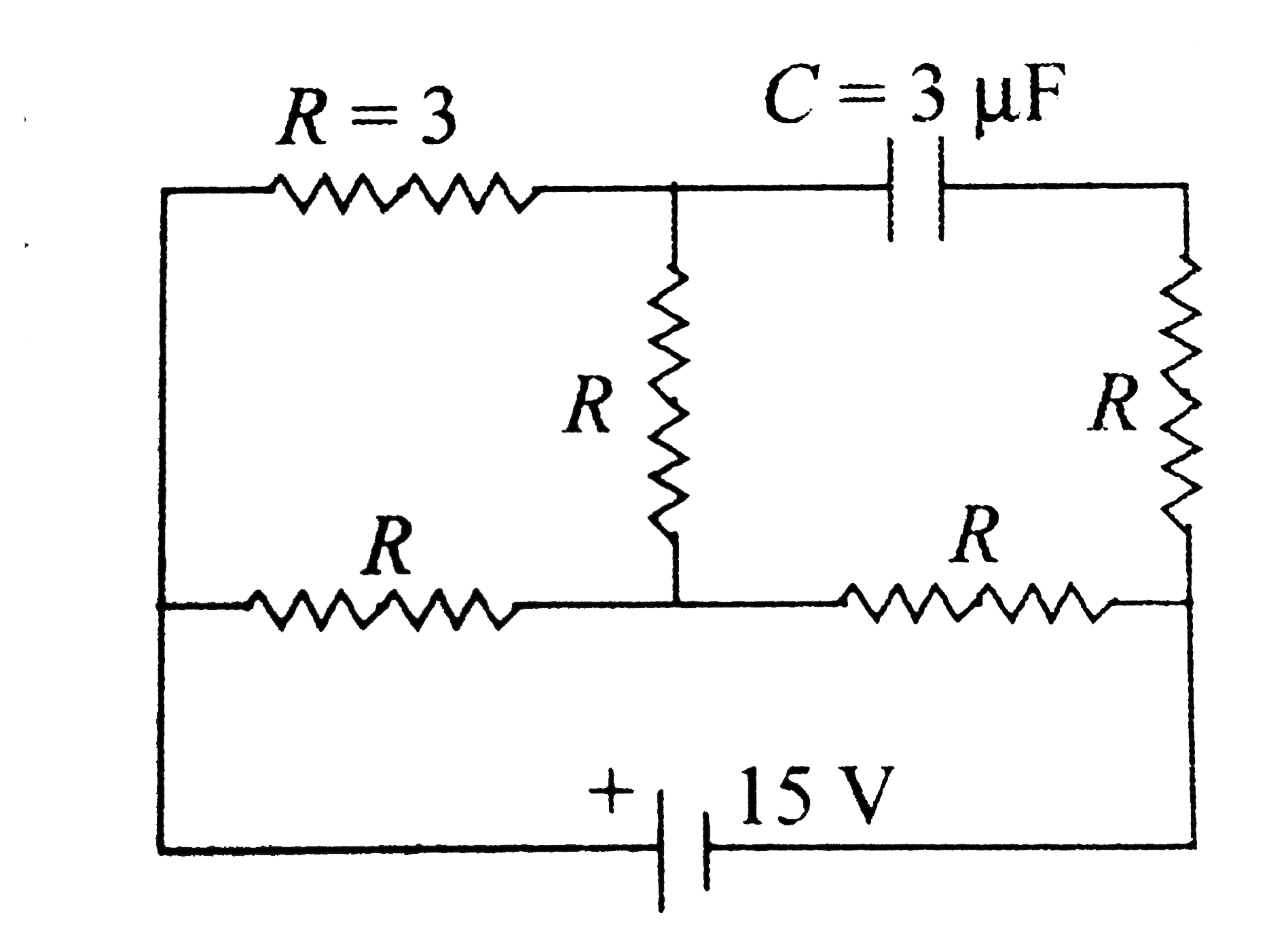
View SolutionIn the circuit shown in fig. the cell is ideal with emf 15V. Each resistance is of 3Ω. The potential difference across the capacitoro in steady state is
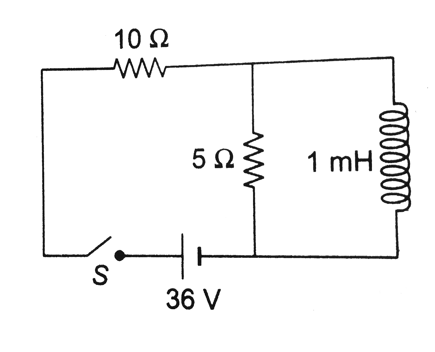
View SolutionIn the circuit arrangement shown in figure, the switch S is closed at t=0. Find the current in the inductance as a function of time? Does the current through 10Ω resistor vary with time or remains constant.
View Solution
