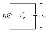
In a circuit consisting of a capacitance and a generator with alternating emf Eg=Eg0sinωt, V_CandI_C are the voltage and current. Correct phasor diagram for such circuit is :


The correct Answer is:B
In pure capacitive circuit, current leads voltage by π/2
Similar Questions
A circuit with capacitance C and inductance L generates free damped oscillations with current varying with time as I=Ime−βtsinωt. Find the voltage across the capacitor as a function of time, and in particular, at the moment t=0.
View SolutionA circuit consists of a resistance 10 ohm and a capacitance of 0.1μF If an alternating e.m.f. of 100 V. 50 Hz is applied, calculate the current in the circuit.
View Solution
Knowledge Check
In an a.c. circuit with voltage V and current I, the power dissipated is
AVIB12VIC1√2VIDdepends on the phase between V and IThe alternating emf of e=e0 sin ωt is applied across capacitor C. the current through the circuit is given by
AI=I0sinωtBI=I0sin(ωt+π2)CI=I0sin(ωt−π2)DI=I0sin(ωt−π)The alternating emf of e=e0 sin ωt is applied across LR series circuit. The impedance and phase angle between current and voltage is
A√R2+X2L,tan−1(XLR)B√R2−X2L,tan−1(XLR)CR+XL,tan−1(RXL)DR−XL,tan−1(RXL)
A circuit consisting of a capacitor with capacitance C and a resistance R connected in series was connected at the moment t=0 to a source of ac voltage V=Vmcosωt . Find the current in the circuit as a function of time t.
View SolutionDraw the phasor diagram for a series RC circuit connected to an a.c. source.
View SolutionA capacitor of capacity C is connected in A.C circuit. If the applied emf is V=V0sinωt, then the current is
View SolutionAn alternating voltage E=E0sinωt , is applied across a coil of inductor L. The current flowing through the circuit at any instant is
View SolutionIf an alternating current i = imsinωt is flowing through a capacitor then voltage drop ΔVC across capacitor C will be
View Solution