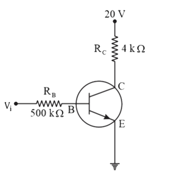
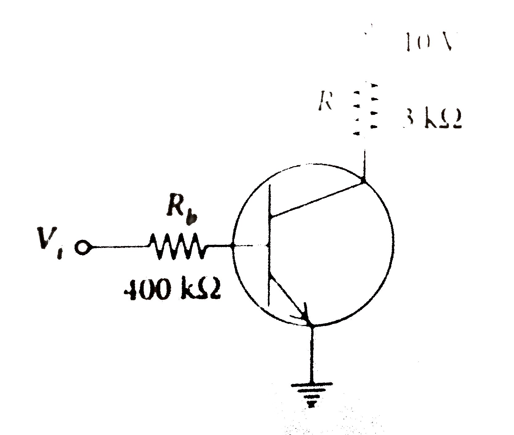
In the circuit shows in the figure, the input voltage
Vi is 20 V, VBE=0 and VCE=0. The values of lB,lC and β are given by
A
IB=40μA, IC=10mA, β=250
B
IB=25μA, IC=5mA, β=250
C
IB=20μA, IC=5mA, β=250
D
IB=40μA, IC=5mA, β=125
Video Solution
Text Solution
The correct Answer is:D
Vi=IBRB+VBE
20=IB×(500×103)+0
IB=20500×103=40μA
VCC=ICRC+VCE
20=IC×(4×10³)+0
IC=5×10−3=5mA
β=ICIB=5×10−340×10−6=125.
|
Topper's Solved these Questions
- ELECTRONICSBOOK - ERRORLESSCHAPTER - ELECTRONICSEXERCISE - Assertion & Reason
26 Videos
- ELECTRONICSBOOK - ERRORLESSCHAPTER - ELECTRONICSEXERCISE - NCERT Based Questions (Digital Electronics)
23 Videos
- ELECTRON, PHOTON, PHOTOELECTRIC EFFECT & X -RAYBOOK - ERRORLESSCHAPTER - ELECTRON, PHOTON, PHOTOELECTRIC EFFECT & X -RAYEXERCISE - ASSERTION & REASON
27 Videos
- ELECTROSTATICSBOOK - ERRORLESSCHAPTER - ELECTROSTATICSEXERCISE - ASSERTION & REASON
25 Videos
Similar Questions
Knowledge Check
In the circuit shown in the figure, the input voltage Vi is 20V,VBE=0 and VCE=0. The values of IB,IC and β are given by:
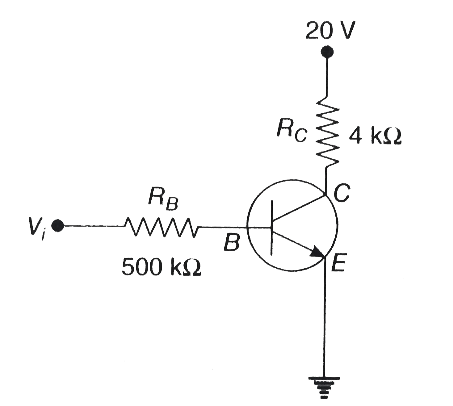 AIB=40μA,IC=10mA,β=250BIB=25μA,IC=5mA,β=200CIB=20μA,IC=5mA,β=250DIB=40μA,IC=5mA,β=125
In the circuit shown in the figure, the input voltage Vi is 20V, VBE=0 and VCE=0. The values of IB, IC and β are given by
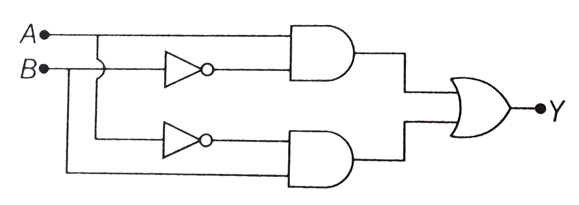 A¯¯¯¯¯¯¯¯A.B+A.BBA.¯¯¯B+¯¯¯A.BC¯¯¯¯¯¯¯¯A.BD¯¯¯¯¯¯¯¯¯¯¯A+B
In the circuit shown in the figure, the input voltage Vi is 20V,VBE=0 and VCE=0. The values of IB,IC and β are given by:
 AIB=40μA,IC=10mA,β=250BIB=25μA,IC=5mA,β=200CIB=20μA,IC=5mA,β=250DIB=40μA,IC=5mA,β=125
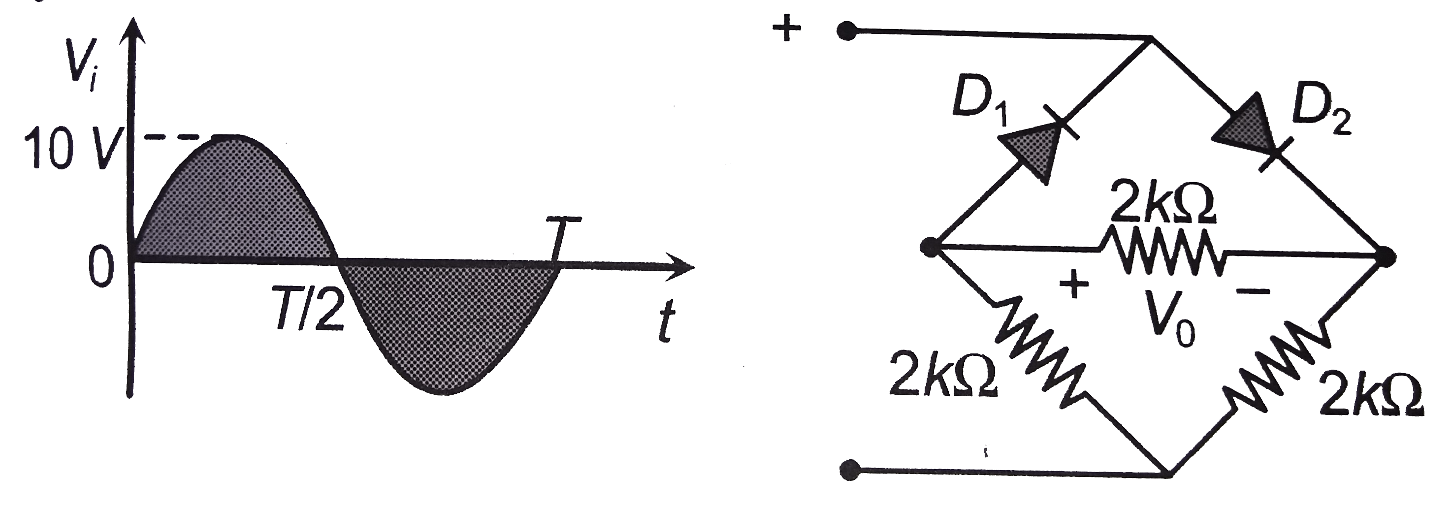
In the circuit shown in figure the maximum output voltage V0 is
View SolutionIn the circuit shown in the figure, the input voltage Vi is 20V,VBE=0 and VCE=0. The values of IB,IC and β are given by:

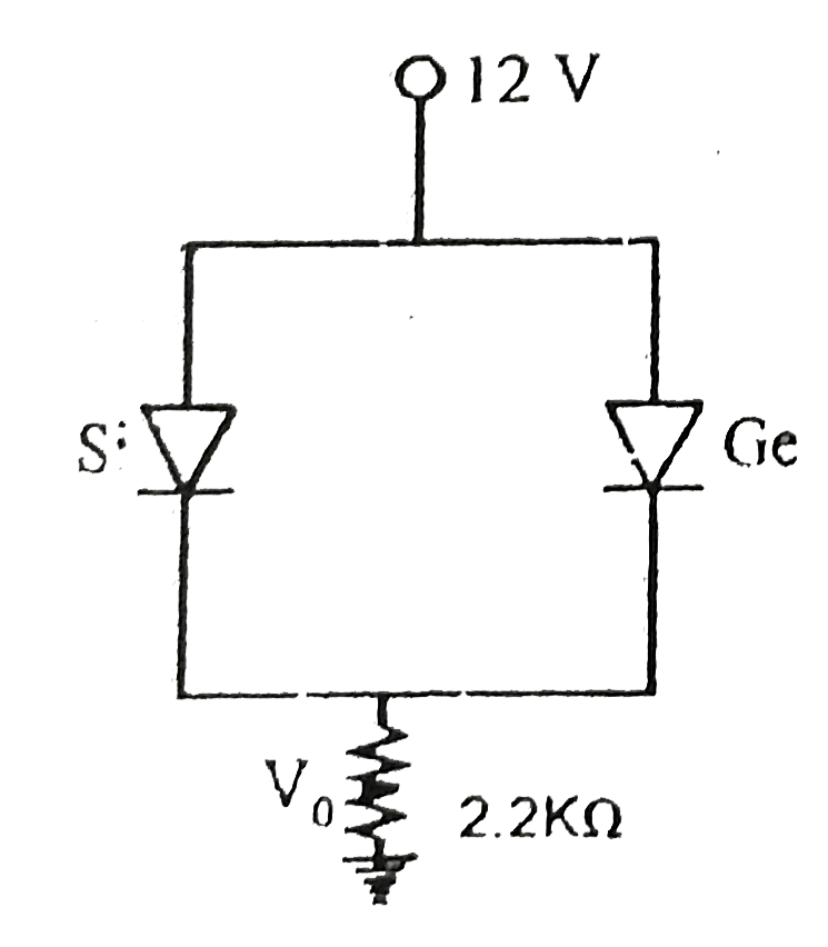
View SolutionIn the circuit shown in figure, Voltage V0 is
View Solution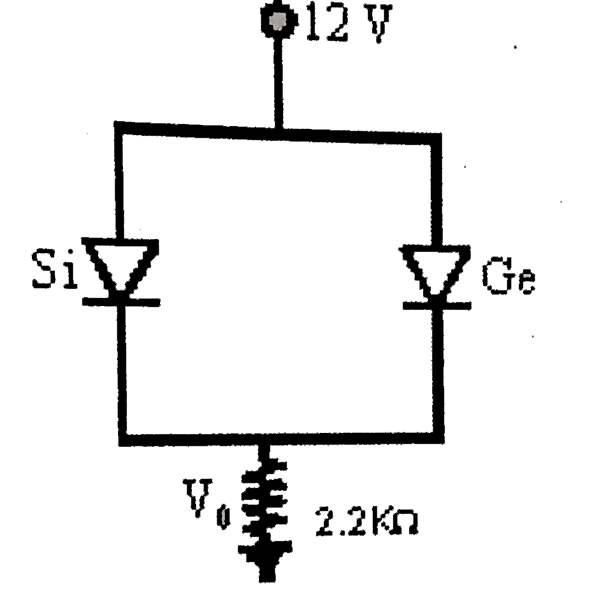
In the circuit shown infigure, voltage V0 is,
View SolutionIn the circuit shown in figure, when the input voltage of the base resistance is 10 V, Vbe is zero and Vce is also zero. Then
View Solution

