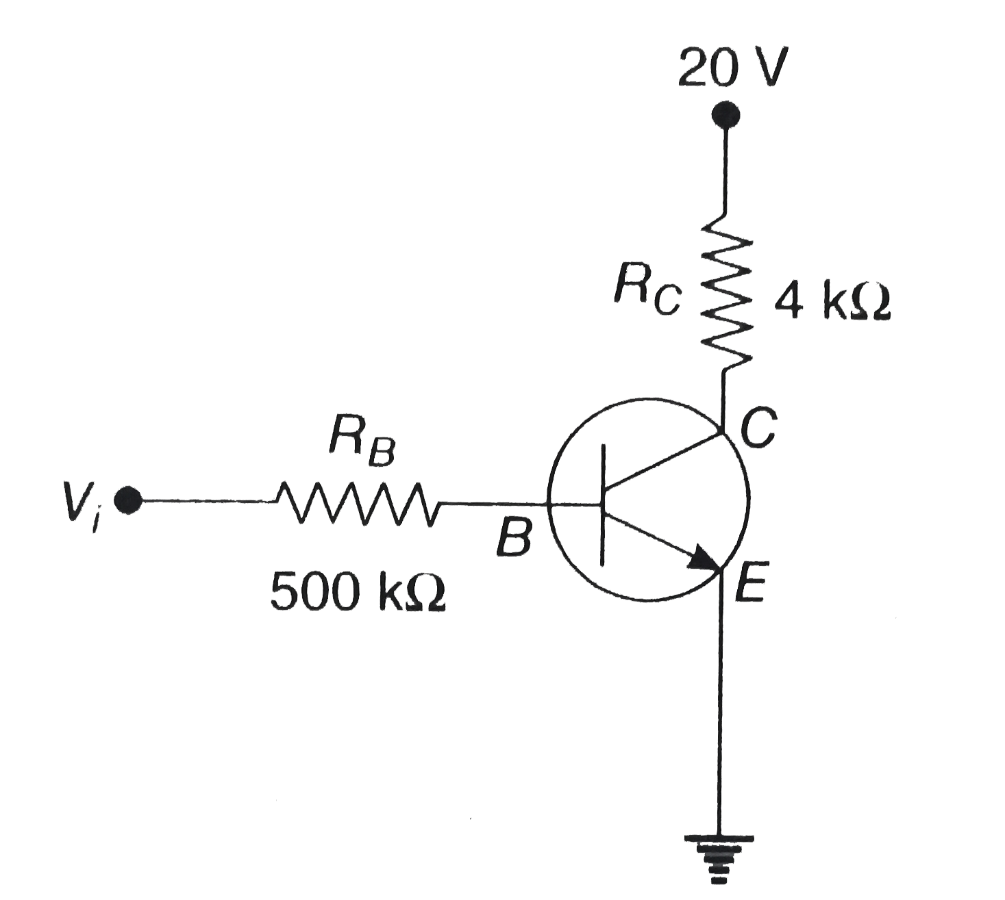
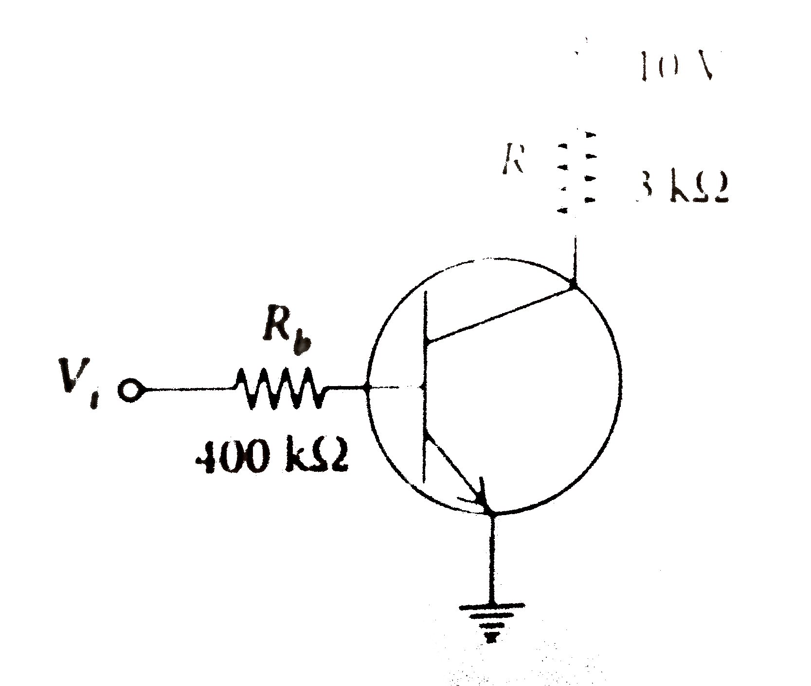
In the circuit shown in the figure, the input voltage is and . The values of and are given by:
A
B
C
D
Video Solution
Text Solution
The correct Answer is:D
From KVL at input side
from KVL at output side
and
|
Topper's Solved these Questions
- SEMICONDUCTOR ELECTRONICS Book:PHYSICS WALLAHChapter:SEMICONDUCTOR ELECTRONICS Exercise:LEVEL-2
Explore 30 Videos
- RAY OPTICS AND OPTICAL INSTRUMENTS Book:PHYSICS WALLAHChapter:RAY OPTICS AND OPTICAL INSTRUMENTS Exercise:NEET PAST 5 YEARS QUESTIONS
Explore 16 Videos
- SYSTEM OF PARTICLES AND ROTATIONAL MOTION Book:PHYSICS WALLAHChapter:SYSTEM OF PARTICLES AND ROTATIONAL MOTION Exercise:NEET PAST 5 YEARS QUESTIONS
Explore 22 Videos
Similar Questions
Knowledge Check
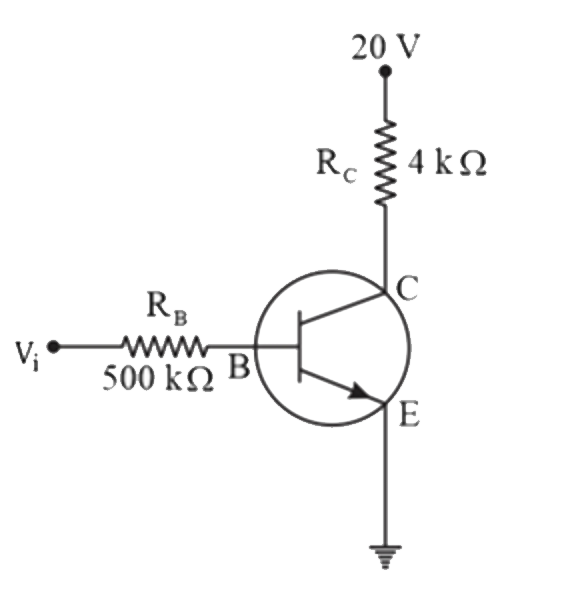
In the circuit shown in the figure, the input voltage Vi is 20V,VBE=0 and VCE=0. The values of IB,IC and β are given by:
 AIB=40μA,IC=10mA,β=250BIB=25μA,IC=5mA,β=200CIB=20μA,IC=5mA,β=250DIB=40μA,IC=5mA,β=125
In the circuit shows in the figure, the input voltage
Vi is 20 V, VBE=0 and VCE=0. The values of lB,lC and β are given by
 AlB=20μA,lC=5mA,β=250BlB=25μA,lC=5mA,β=200ClB=40μA,lC=10mA,β=250DlB=40μA,lC=5mA,β=125
In the circuit shown in figure the maximum output voltage V0 is
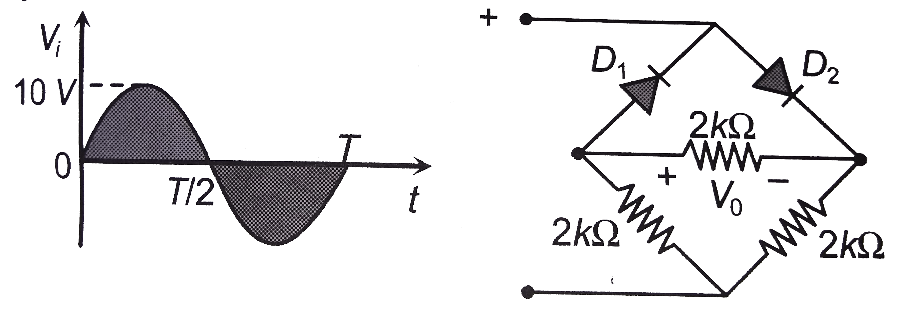 A0VB5VC10VD5√2V
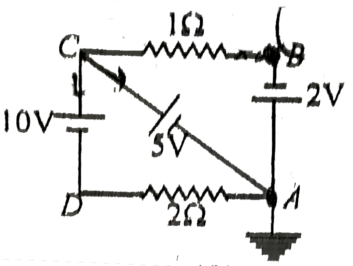
In the circuit shown in the figure, the ratio of VB as VC is
View SolutionIn the circuit shown in the figure, the input voltage Vi is 20V,VBE=0 and VCE=0. The values of IB,IC and β are given by:

View SolutionIn the circuit shown in figure, Voltage V0 is
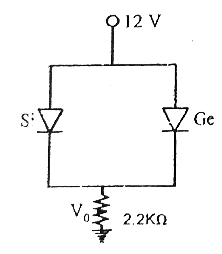
View Solution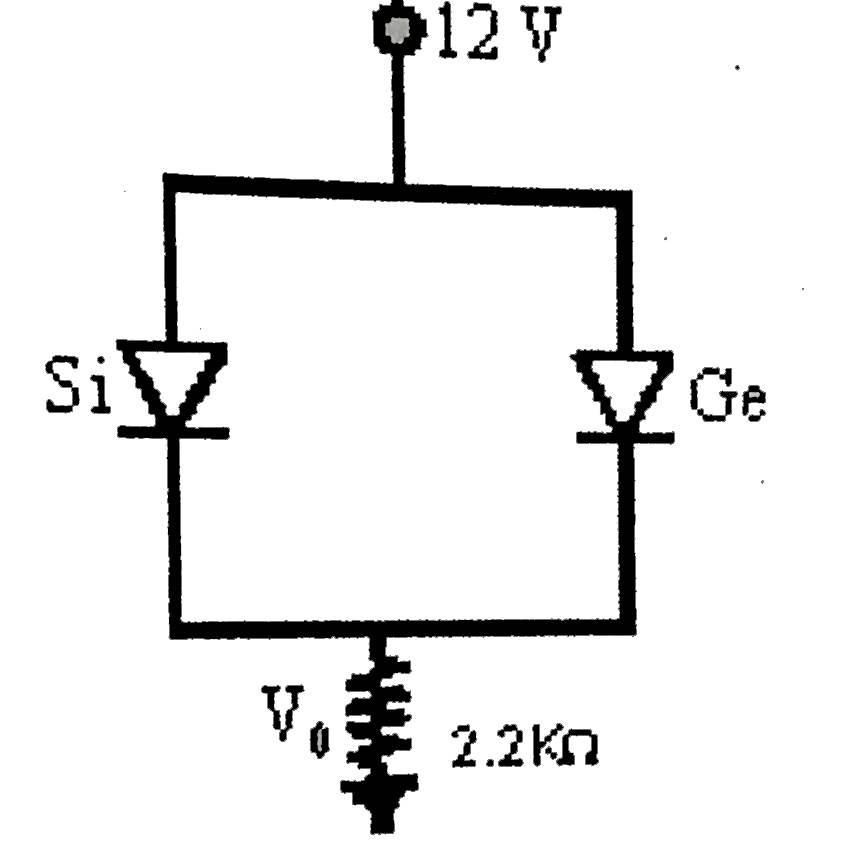
In the circuit shown infigure, voltage V0 is,
View SolutionIn the circuit shown in figure, when the input voltage of the base resistance is 10 V, Vbe is zero and Vce is also zero. Then
View Solution
