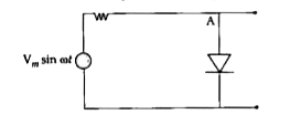
The output of the given circuit in Figure
A
would be zero at all times.
B
would be like a half wave rectifier with positive cycles in output.
C
would be like a half wave rectifier with negative cycles in output.
D
would be like that of a full wave rectifier.
Video Solution
Text Solution
The correct Answer is:C
When A is the positive terminal, the diode is said to be in forward resistance and resistance would be zero. The potential difference across the diode is noted to be in forward bias and we record a pulsating voltage, varying from '0' to 'V_(m)', in a sinosodal manner. When A is the negative terminal, the diode is said to be reverse biased and the circuit is an open circuit with resistance being maximum and current being zero. Hence, the circuit acts as a 'half wave rectifier' with positive cycles in output. Hence, the answer is 'B'.
|
Updated on:21/07/2023
Similar Questions
Knowledge Check
- Question 1 - Select One
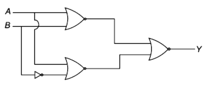
The output for the given, circuit is
 A(A+B)⋅¯¯¯BB(A⋅B)⋅¯¯¯BC(A+B)⋅BD(A⋅B)⋅B
 - Question 2 - Select One or More
In the given circuit figure
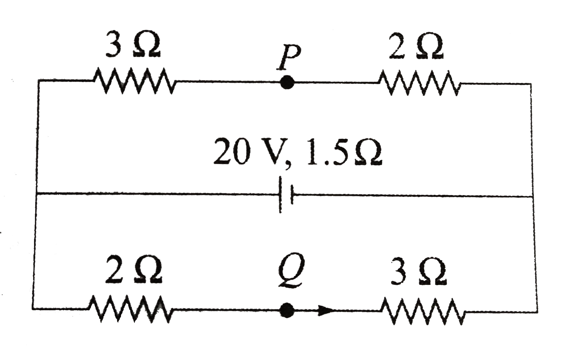 Athe current through the battery is 5.0 ABP and Q are at the same potentialCP is 2.5 V higher than QDQ is 2.5 V higher than P
 - Question 3 - Select One
If the given diode is ideal, the output of the given circuit in
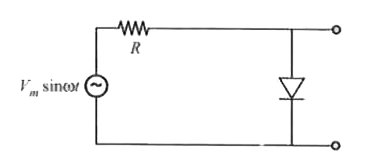 Awould be zero at all times.Bwould be like a half wave rectifier with positive cycles in output.Cwould be like a half wave rectifier with negative cycles in output.Dwould be like that of a full wave rectifier.

