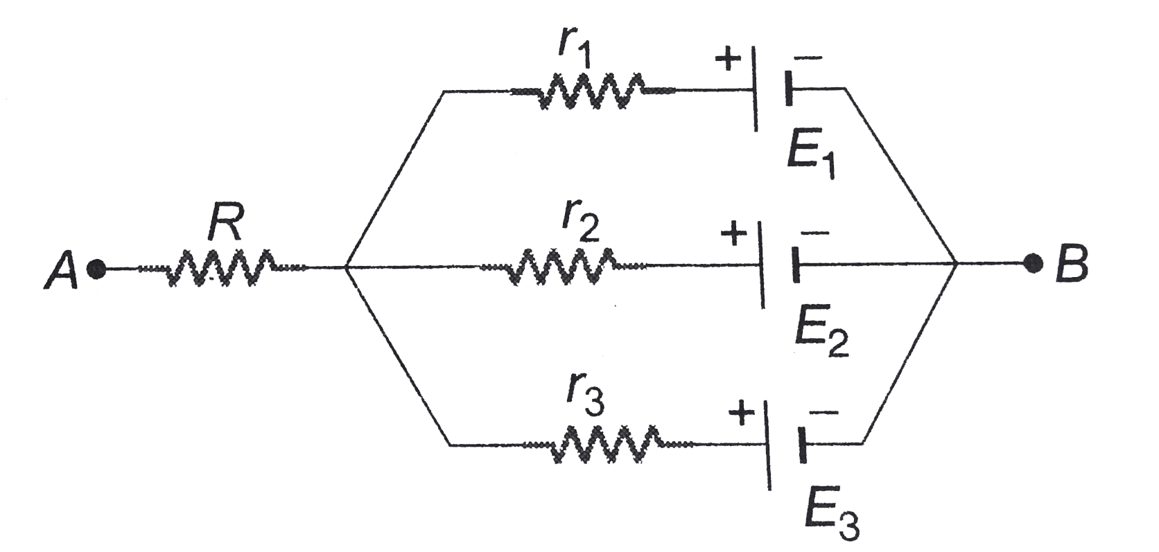
In the circuit shown in figure

E1=10V,E2=4V,r1=r2=1Ω and R=2Ω.
Find the potential difference across battery 1 and battery 2.
5.5 V each
8.5 V each
5.5 V, 8.5 V
8.5 V, 5.5 V
The correct Answer is:D
Net emf of the circuit =E1−E2=6V
Total resistance of the circuit =R+r1+r2=4Ω
∴ Current in the circuit, i=net emftotal resistance=64=1.5A
Now, V1=E1−ir1=10−(1.5)(1)=8.5V
and V2=E2+ir2=4+(1.5)=5.5V

Similar Questions
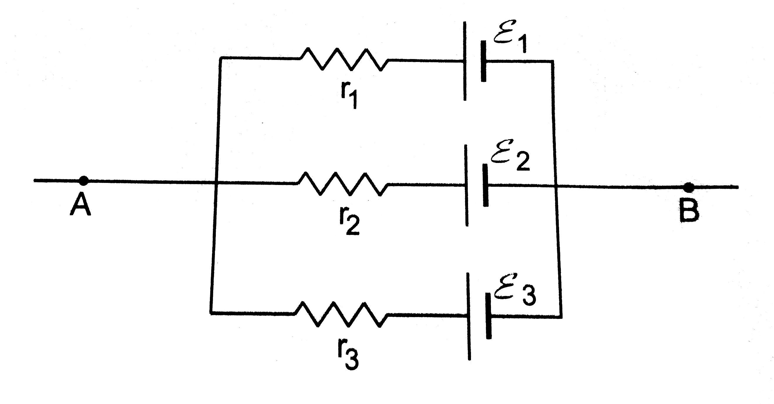
In the circuit shown in figure ,(ε)1=3V,(ε)2=2V,(ε)3=1Vandr1=r2=r3=1(Ω).Find the potential difference between the points A and B and the current through each branch.
View SolutionIn the circuit in figure E1=3V,E2=2V,E3=1V and R=r1−r2−r3=1Ω
a. Find the potential differece between the points A and B and the currents through each branch.
b. If r2 is short circuited and the point A is connected to point B, find the currents through E1,E2,E3 and the resistor R
View Solution
Knowledge Check
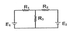
In the circuit shown, E1=7V,E2=7V,R1=R2=1Ω and R3=3Ω respectively. The current through the resistance R3
 Ai=0Bi=2ACV=14VDV=7V
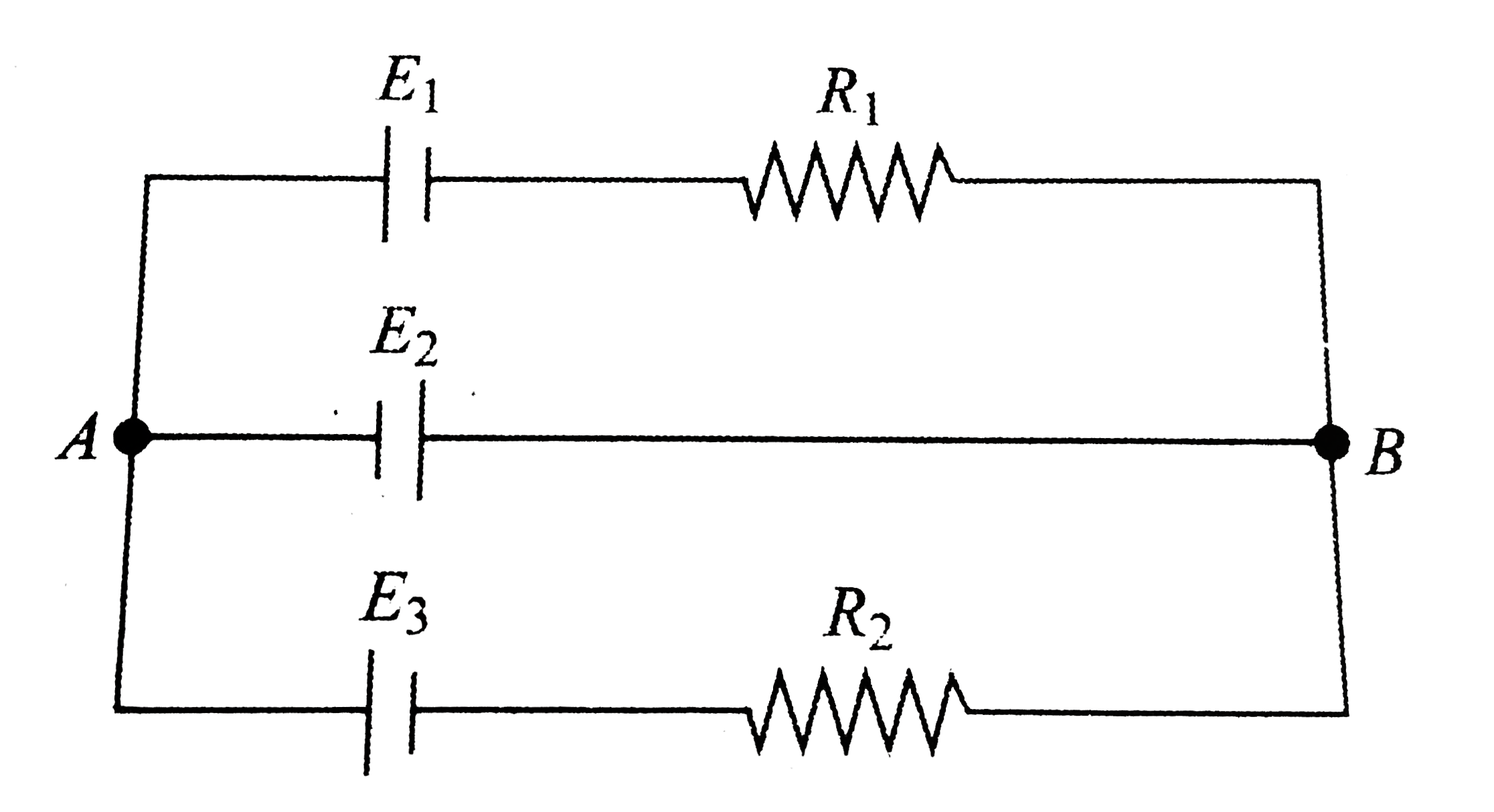
In the circuit shown in fig. 5.265, E1=E2=E3=2V and R1=R2=4Ω. The current flowing between points A and B through battery E2 is
 AzeroB2 A from A to BC2 A form B to ADnone of the above
In the circuit shown in figure ammeter and voltmeter are ideal. If E=4V,R=9Ω and r=1Ω then readings of ammeter and voltmeter are
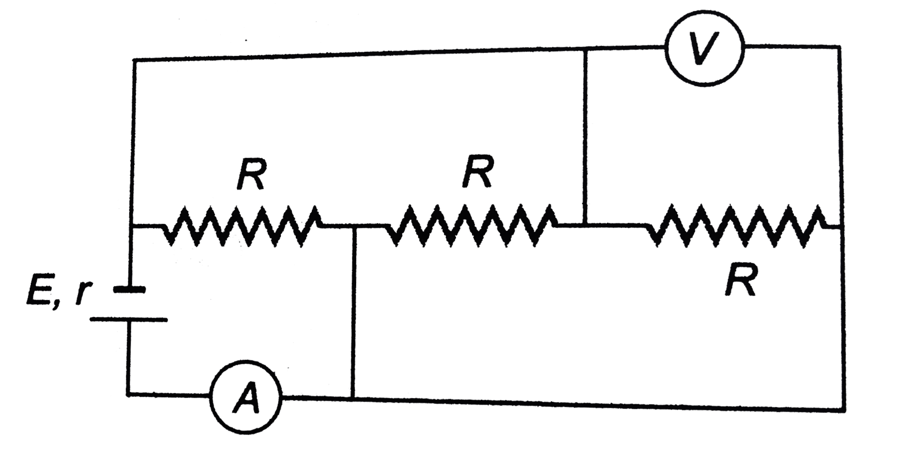 A1A,3VB2A,3VC3A,4VD4A,4V
In the circuit as shown in figure,
E1=2V,E2=2V,E3=1V,andR=r1=r2=r3Ω.
The potential difference between points A and B will be

View SolutionIn the circuit shown in figure E1=7V,E2=1V,R1=2Ω,R2=2Ω and R3=3Ω respectively. Find the power supplied by the two batteries.
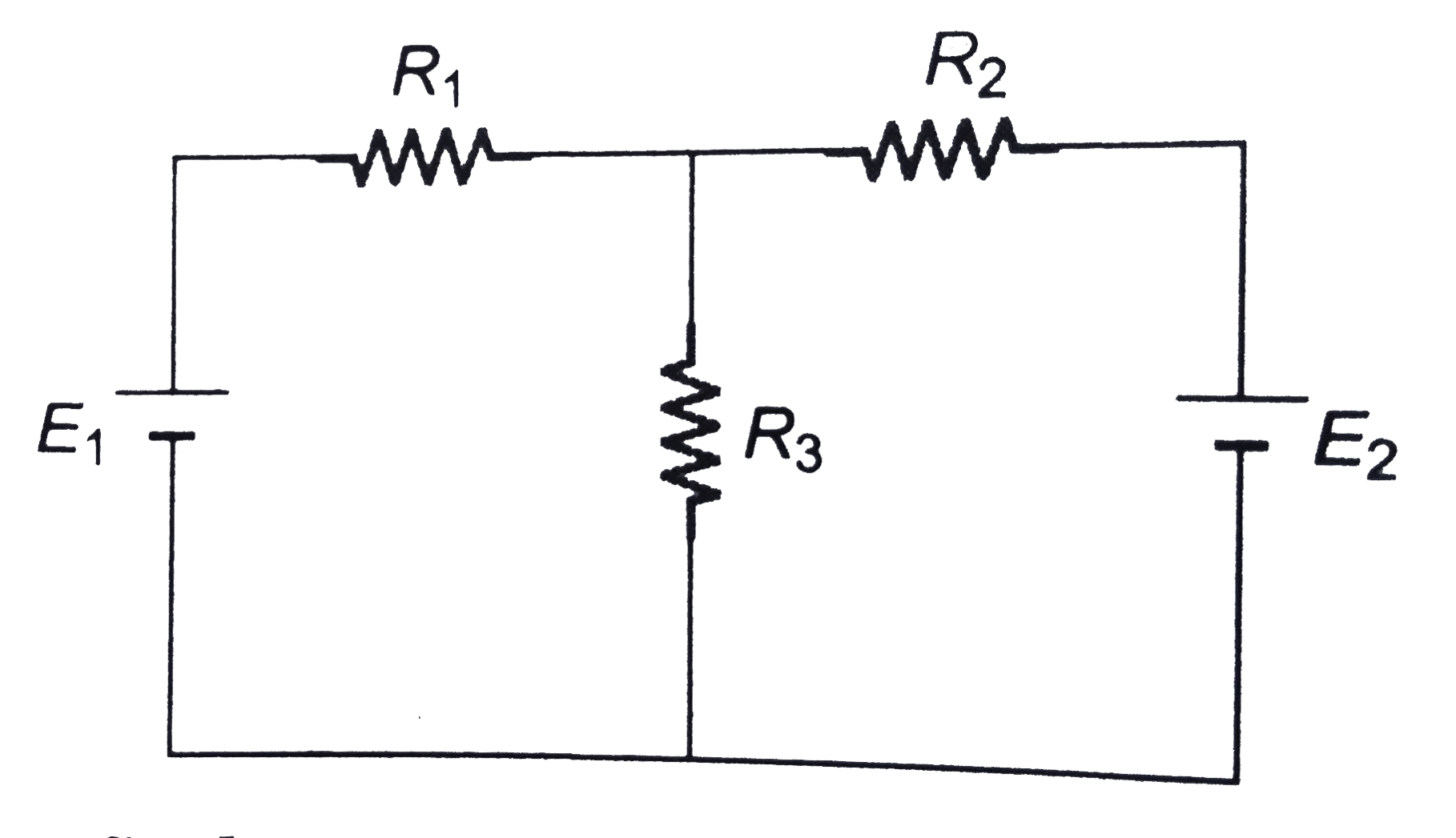
View SolutionIn the circuit shown in fig. E1=3 volt,E2=2 volt,E3=1 vole and R=r1=r2=r3=1ohm.
(i) Find potential difference in Volt between the points A and B with A & B unconnected.
(ii) If r2 is short circuited and the point A is coneted to point B through a zero resistance wire, find the current through R in ampere.
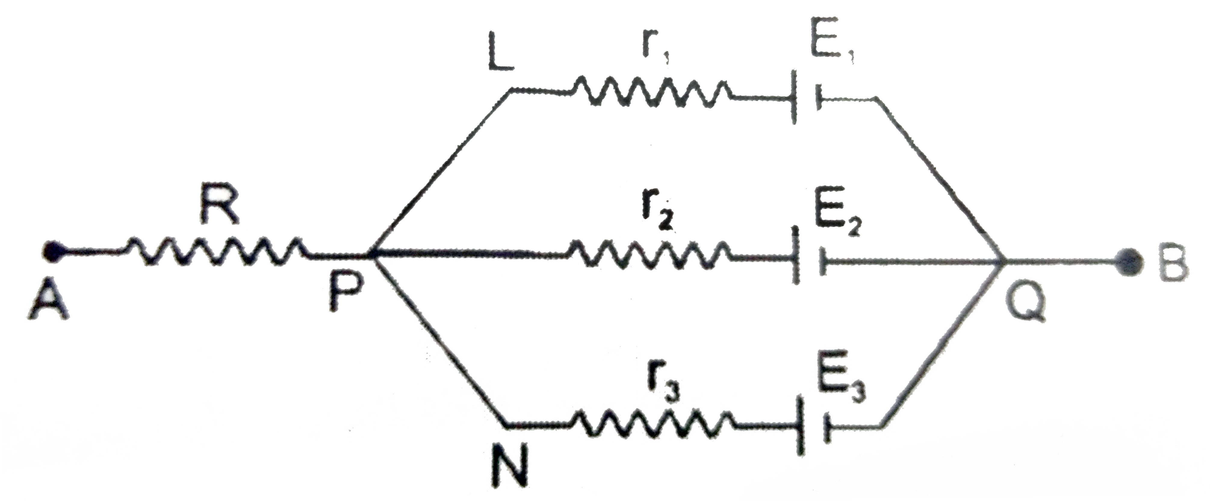
View SolutionIn the circuit shown in figure ,(ε)1=3V,(ε)2=2V,(ε)3=1Vandr1=r2=r3=1(Ω).Find the potential difference between the points A and B and the current through each branch.

View SolutionIn the circuit shown in figure E1,2E2=20V,R1=R2=10kΩ and C=1μF. Find the current through R1,R2 and C when
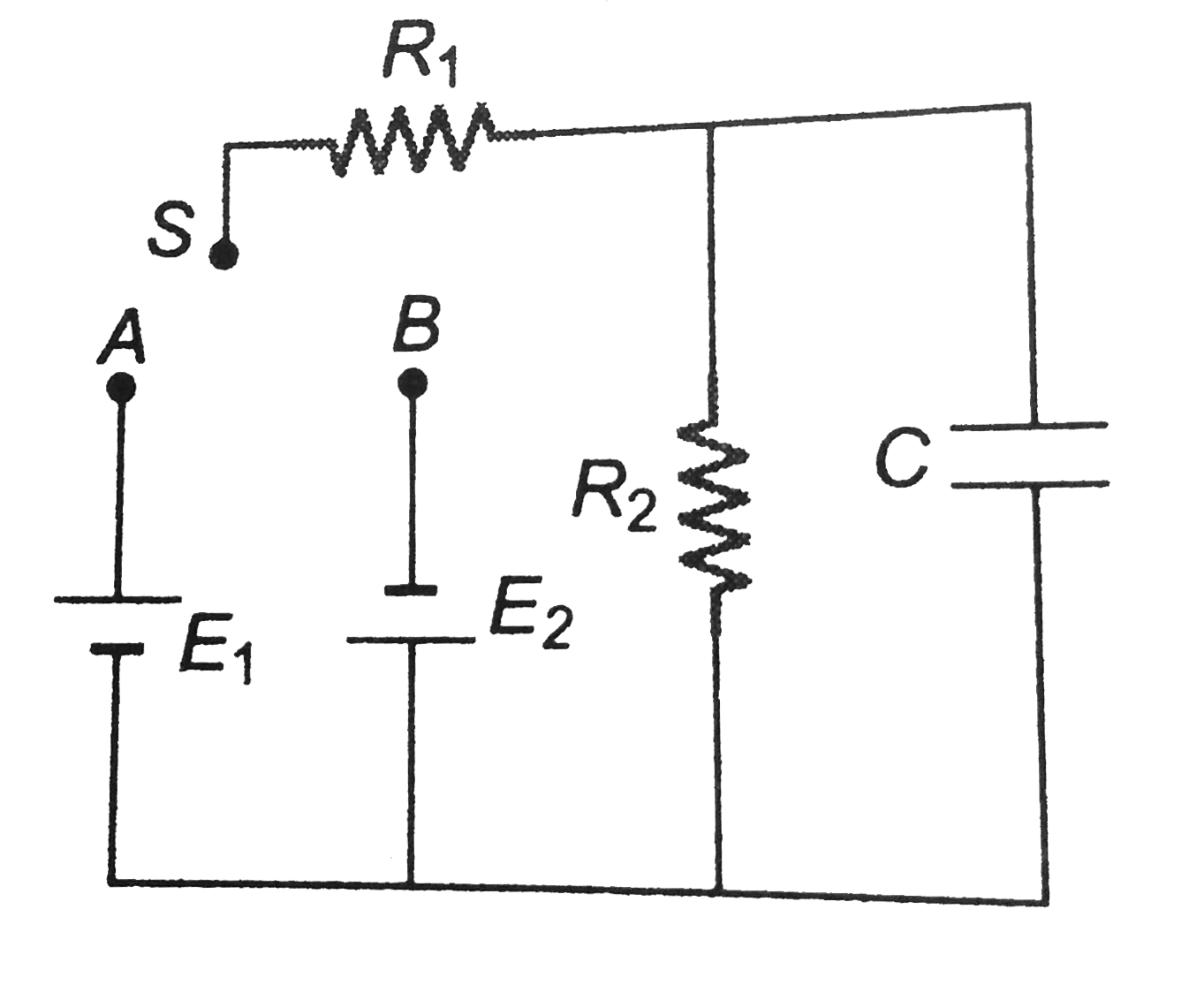
(a) S has been kept connected to A for a long time.
(b) The switch is suddenly shifted to B.
View Solution
