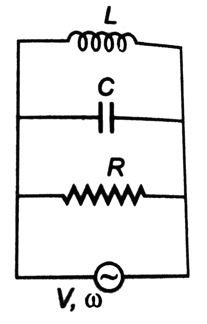
A given LCR series circuit satisfes the condition for resonance with a given AC source. If the angular frequency of the AC source is increased by 100% then in order to establish resonance, and without changing the value of inductance, capacitance must be
Increased by 100%
Reduced by 50%
Increased by 75%
Reduced by 75%
To solve the problem step-by-step, we need to analyze the conditions for resonance in an LCR circuit and how changing the angular frequency affects the capacitance.
1. Understand the Resonance Condition:
In an LCR series circuit, resonance occurs when the inductive reactance equals the capacitive reactance. The condition for resonance is given by:
ωL=1ωC
Rearranging gives:
ω2=1LC
2. Initial Conditions:
Let the initial angular frequency be ω and the initial capacitance be C. Thus, we have:
ω2=1LC
3. Change in Angular Frequency:
The problem states that the angular frequency is increased by 100%. Therefore, the new angular frequency ω′ becomes:
ω′=2ω
4. New Resonance Condition:
For the new frequency, the resonance condition becomes:
ω′L=1ω′C′
Substituting ω′=2ω:
2ωL=12ωC′
5. Rearranging for Capacitance:
Rearranging the equation gives:
C′=14ω2L
6. Substituting for ω2:
From the initial condition, we know:
ω2=1LC
Substituting this into the equation for C′:
C′=14⋅1LC=C4
7. Finding the Change in Capacitance:
The new capacitance C′ is C4. The change in capacitance ΔC is:
ΔC=C−C′=C−C4=3C4
8. Calculating Percentage Change:
The percentage change in capacitance is given by:
Percentage Change=ΔCC×100=3C4C×100=34×100=75%
Since C′ is less than C, this represents a decrease.
Conclusion:
The capacitance must be reduced by 75% in order to establish resonance after the angular frequency is increased by 100%.
In an LCR series circuit, resonance occurs when the inductive reactance equals the capacitive reactance. The condition for resonance is given by:
ωL=1ωC
Rearranging gives:
ω2=1LC
Let the initial angular frequency be ω and the initial capacitance be C. Thus, we have:
ω2=1LC
The problem states that the angular frequency is increased by 100%. Therefore, the new angular frequency ω′ becomes:
ω′=2ω
For the new frequency, the resonance condition becomes:
ω′L=1ω′C′
Substituting ω′=2ω:
2ωL=12ωC′
Rearranging the equation gives:
C′=14ω2L
From the initial condition, we know:
ω2=1LC
Substituting this into the equation for C′:
C′=14⋅1LC=C4
The new capacitance C′ is C4. The change in capacitance ΔC is:
ΔC=C−C′=C−C4=3C4
The percentage change in capacitance is given by:
Percentage Change=ΔCC×100=3C4C×100=34×100=75%
Since C′ is less than C, this represents a decrease.
The capacitance must be reduced by 75% in order to establish resonance after the angular frequency is increased by 100%.
Similar Questions
For an LCR series circuit with an ac source of angular frequency ω.
View SolutionFor an LCR series circuit with an aac source of angular frequency ω.
View SolutionA bulb and a conender are connected in series with an A.C source. On increasing the frequency of the source its brightness will
View SolutionIn series LCR circuit voltage leads the current. When
(Given that ω0 = resonant angular frequency)
View SolutionConsider in L−C−R circuit as shown in figureure with an AC source of peak value V0 and angular frequency ω. Then the peak value of current through the AC
 .
.
View SolutionAn LCR series circuit is in resonance with the frequency of applied ac generator. Select the incorrect statement:
View SolutionIn a series LCR circuit resonance of frequency is the half of the frequency of source.The nature of the circuit is
View SolutionIn a series LCR circuit, operated with an ac of angular frequency ω , the total impedance is
View SolutionA series LCR circuit containing a resistance of 120Ω has angular resonance frequency 4×10⁵rads−1. At resonance the vlotage across resistance and inductance are 60V and 40 V, repectively,
the value of inductance L is
View SolutionA series LCR circuit with L=4.0H,C=100μF and R=60Ω is connected to a variable frequency 240 V source. Calculate
(i) angular frequency of the source which drives the circuit in resonance,
(ii) current at the resonating frequency,
(iii) rms potential drop across the inductance at resonance.
View Solution