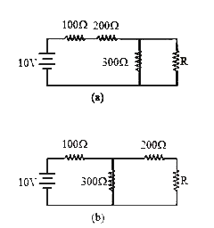
A student was trying to construct the circuit shown in the figure below maked (a), but ended up constructing the circuit marked (b). Realizing her mistake, she corrected the circuit , but to her surprise, the output voltage (across R) did not change.
The value of resistance R is :-
100 Ω
150Ω
200Ω
300Ω
The correct Answer is:A
For circuit (a),
iR=⎛⎜⎝10300R300+R+300×300300+R⎞⎟⎠
Current through cell
[Note : 300 Ω & R are in parallel which is in series with 100&200Ω]
∴VRa=10×300R300R+3002+300R
[VRa is potential difference across resistance R]
For circuit (b),
iR=(10(200+R)(300)/(200+R+300)+100)×300300+200+R
Current through cell
[Note : R & 200 Ω are in series which is in parallel with 300 Ω & again the combination is in series with 100 Ω]
∴VRb=100×300R300×200×300R+100×500+100R
[ VRb is potential difference across resistance R]
According to given situtaion
VRa=VRb
∴300R+9×10⁴+300R=6×10⁴+400R+5×10⁴
⇒200R=2×10⁴⇒R=100Ω
Topper's Solved these Questions
Similar Questions
A student was trying to constant the circuit shown in the figure below marked (a), but ended up constructing the circuit marked (b). Realizing her mistake, she corrected the circuit, but the her surpris, the output voltage (across R) did not change

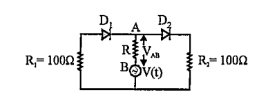
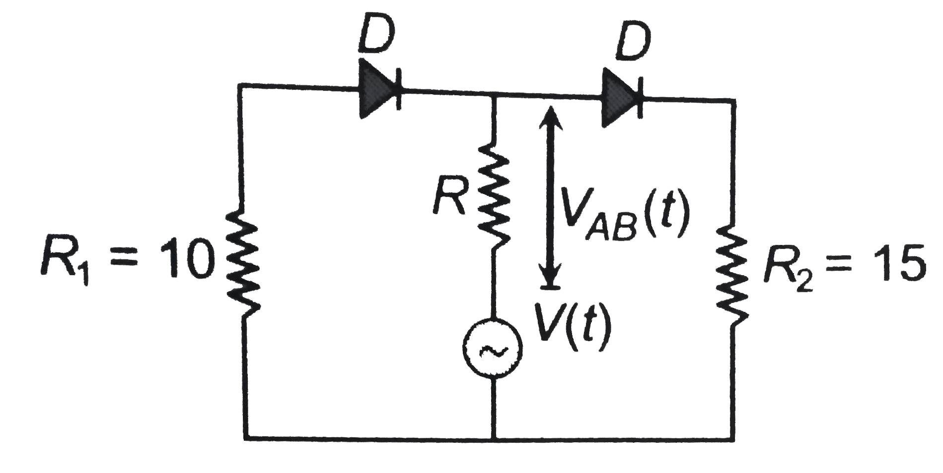
View SolutionIn the circuit given below, V(t) is the sinusoidal voltage source, voltage drop VAB(t) across the resistance R is
View Solution
Knowledge Check
In the circuit shown in figure the total resistance between points A and B is R0. The value of resistance R is
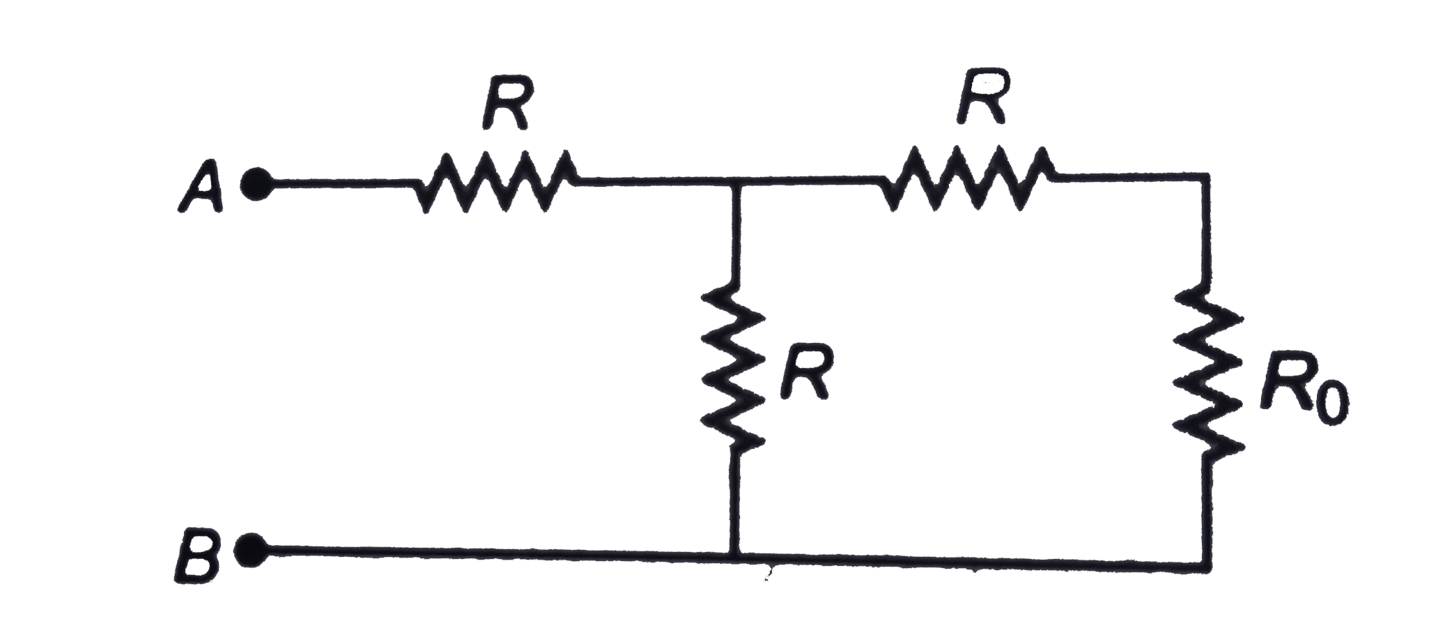 AR0B√3R0CR02DR0√3
In the circuit shown in the figure, the value of maximum rate of heat production in resistance R is
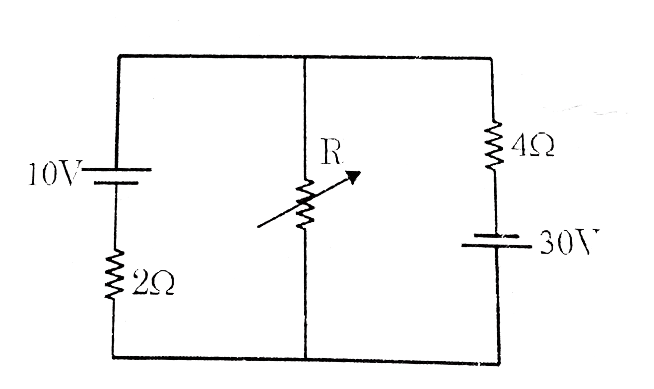 A2512WB3812WC3512WDNone
In the circuit given below, V(t) is the sinusoidal voltage source, voltage drop VAB(t) across the resistance R is
 Ais half wave rectifiedBis full wave rectifiedChas the same peak value in the positive and negative half cyclesDhas different peak values during positive and negative half cycle
In the circuit given below, V(t) is the sinusoidal voltage source, voltage drop VAB(t) across the resistance R is
View SolutionIn the circuit shown below, the ammeter reading is zero. Then, the value of the resistance R is
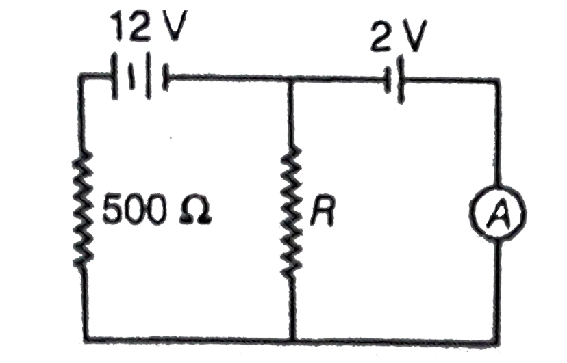
View SolutionIn the circuit shown below, the ammeter reading is zero. Then, the value of the resistance R is

View SolutionIn the circuit shown below, the ammeter A reads 5 A and the voltmeter V reads 20 V The correct value of resistance R is

View SolutionIn the circuit shown in figure resistance of each wire is r. Net resistance across

View Solution
