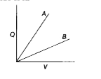
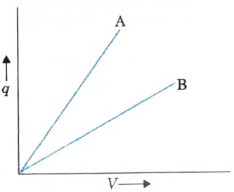
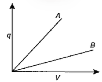
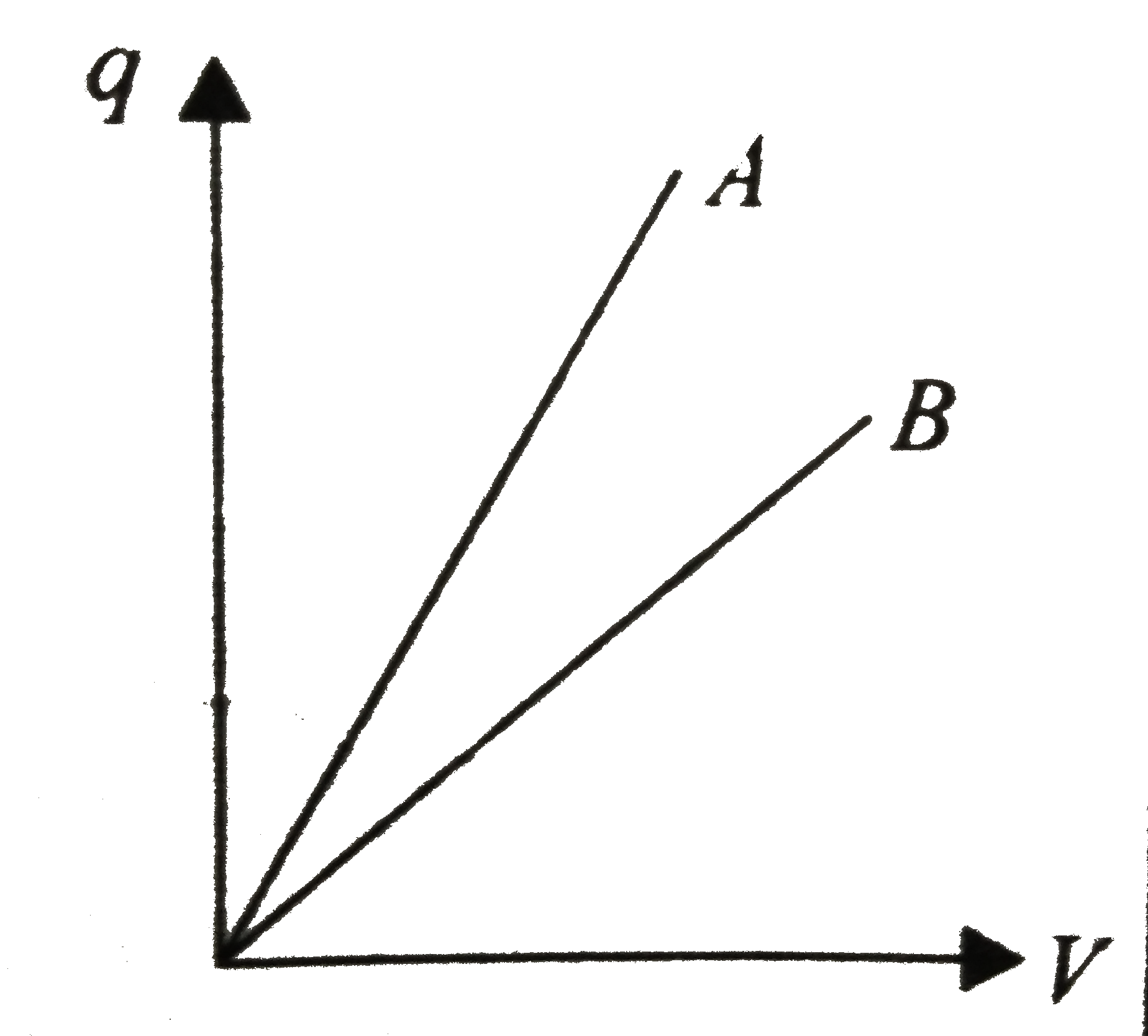
The given graph shows the variation of charge Q versus potential difference for capacitances C2 and C2. The two capacitors have the same plate separation but the plate area of C2 is double that of C1. Which of the lines in the graphs correspond to C1 and C2 and why ?
 Solution in Odia
Line B corresponds to C1 because slop (Q/V) of B is less than slop of A.

Similar Questions
Two capacitors of capacitances C_(1) and C_(2) are connected in parallel. If a charge q is given to the assembly, the charge gets shared. The ratio of the charge on the capacitor C_(1) to the charge on C_(2) is
View SolutionTwo capacitors C1andC2 have the same separation between the plates but the plate area of C2 is twice that of C1. The given graph shows the variation of q with V. Which of the two lines in the graph represents C1 and why?

View SolutionTwo capacitors of capacitances C1 and C2 are connected in parallel. If a charge Q is given to the combination, the ratio of the charge on the capacitor C1 to the charge on C2 will be
View SolutionA capacitor of capacity C1=1μF is charged to a potential of 100 V. The charging battery is then removed and it is connected to another capacitor of capacity C2=2μF. One plate of C2 is earthed as shown in figure. The charges on C1andC2 in steady state will be

View SolutionIn the network of capacitors given ahead. Find the effective capacitance between point P and Q
If C1=C2=C3=C4=4μF
Value is not given C1andC2

View SolutionThe given graph shows variation of charge .q. versus potential difference .V. for two capacitors

C1andC2. Both the capacitors have same plate separation but plate area of C2 is greater than that of C1. Which line (A or B) corresponds to C1 and why?
View SolutionShows these variation of charge q for two capacitors C1 and C2 The two capacitors have the same plate separation. But the plate area of C2 is double than that of C1. Which of the lines in the figure corresponds to C1 and C2 and why?
 .
.
View SolutionTwo identical capacitors C_(1) And C_(2) The batteries are added in series. They are fully charged. Now capacitor to dielectric plate C_(2) Let's insert it between the plates. C_(1) Potential at the ends of -
View Solution