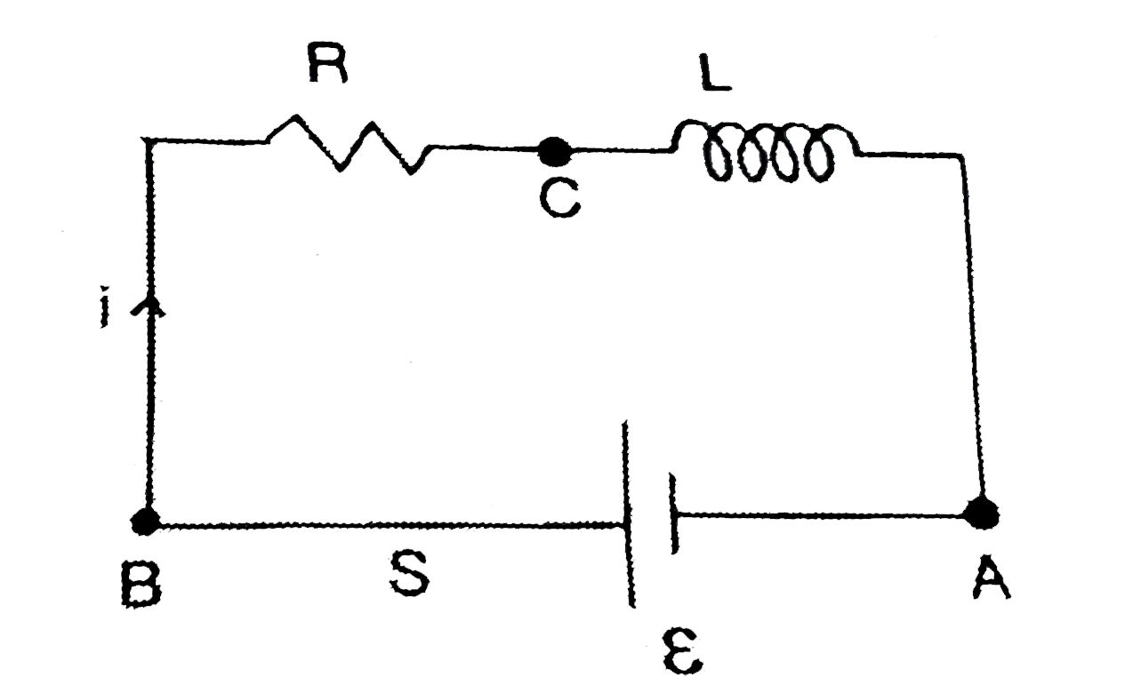
Figure shows a circuit consisting of a ideal cell, an inductor L and a resistor R connected in series.Let the switch S be closed at t=0.Suppose at t=0 current in the inductor is i0 then find out equation of current as a function of time.
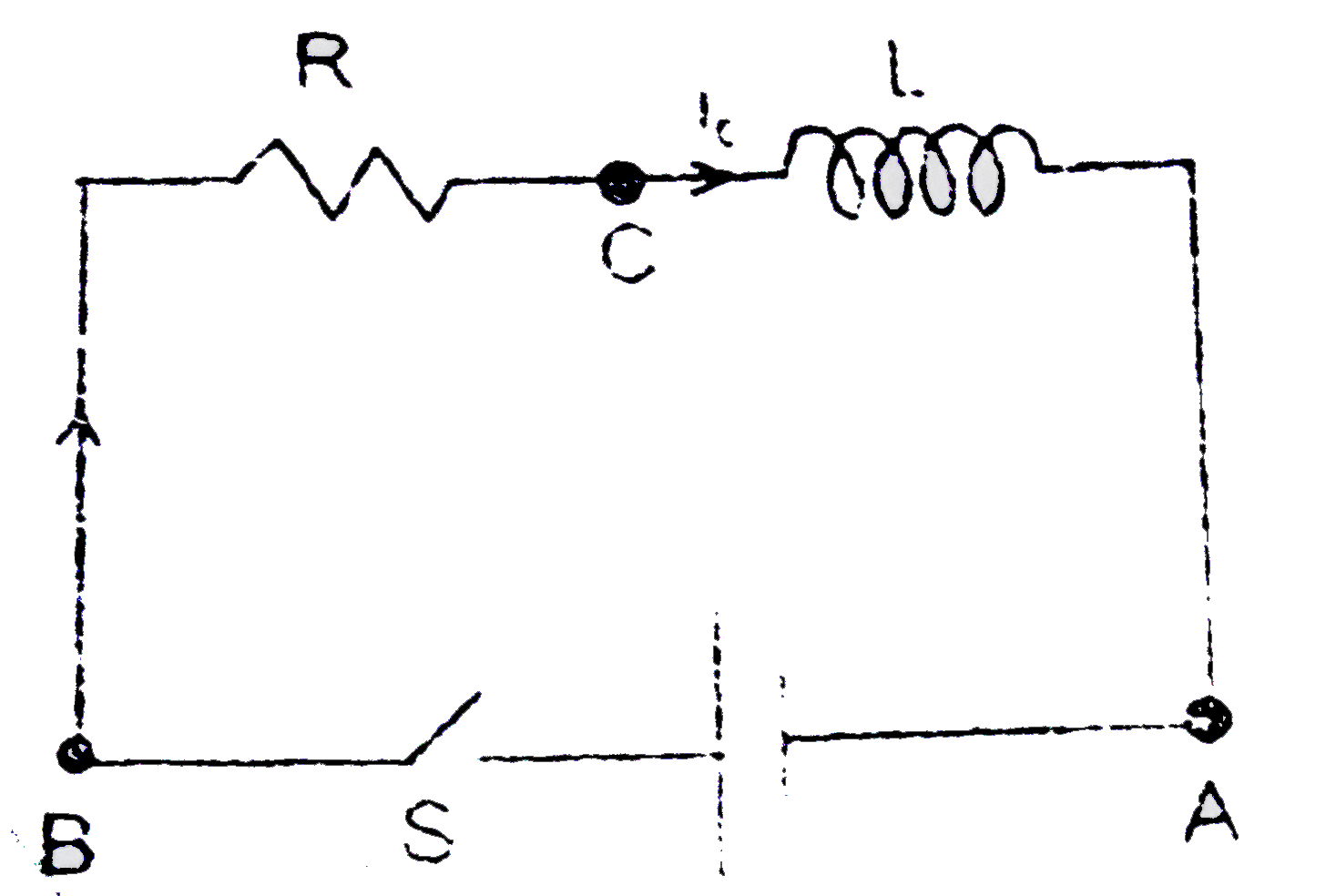
Let an instant t current in the circuit is i which is increasing at the rate di/dt.
Writing KCL along the circuit, we have ε−LdiDt−iR=0
⇒Ldidt=ε−iR⇒∫ii0diε−iR=∫t0dtL
⇒In(ε−iRε−i0R)=−RtL⇒ε−iR=(ε−i0R)e−Rt/L⇒i=ε−(ε−i0R)e−Rt/LR
Similar Questions
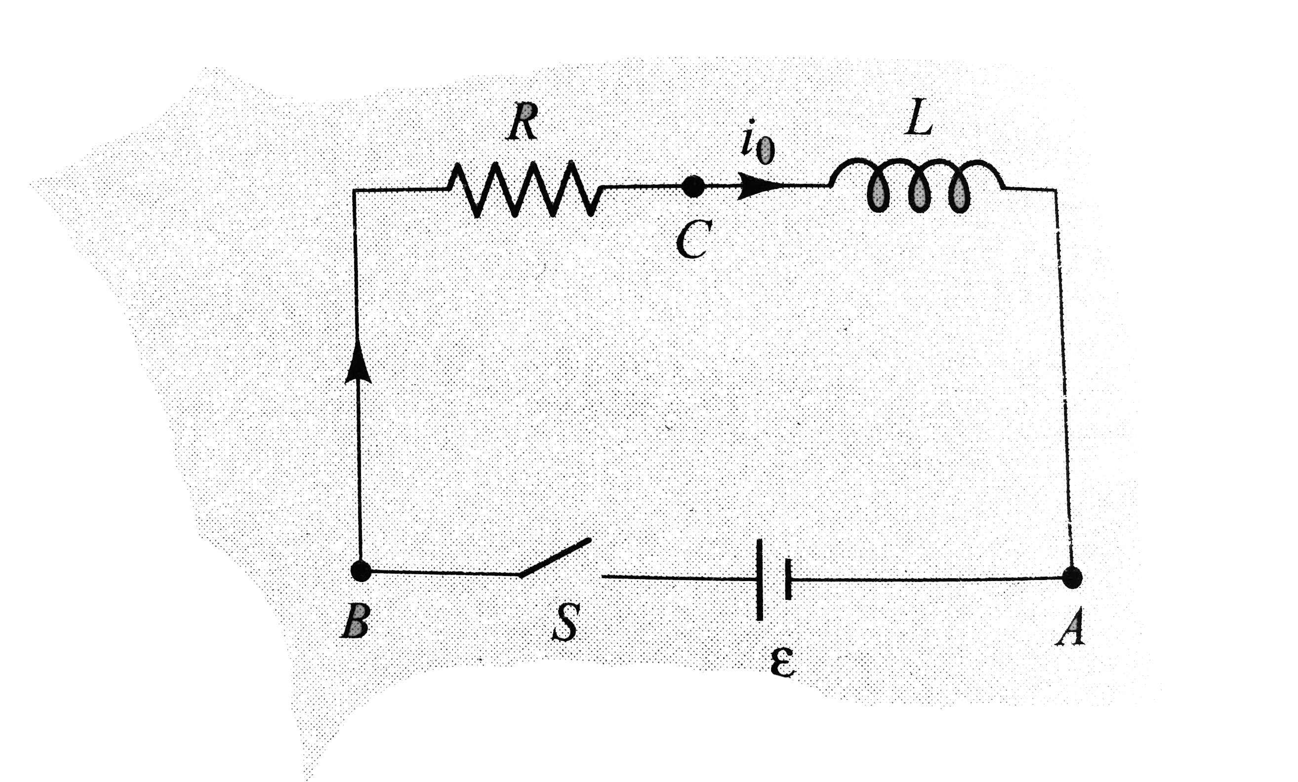
Figure shows a circuit consisting of an ideal cell, an inductor L, and a resistor R, connected in series. Let switch S be closed at t=0. Suppose at t=0, the current in the inductor is io, then find out the equation of current as a function of time.
View SolutionFigure shows a circuit consisting of an ideal cell, an inductor L, and a resistor R, connected in series. Let switch S be closed at t=0. Suppose at t=0, the current in the inductor is io, then find out the equation of current as a function of time.

View SolutionTwo inductors are connected in parallel and switch S is closed at t=0

View SolutionThe switch in figure is closed at time t=0. Find the current in the inductor and the current through the switch as functions of time thereafter.
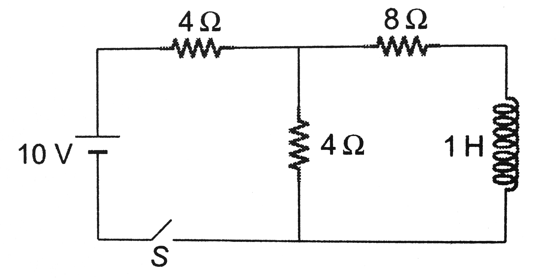
View SolutionIn the following circuit the switch is closed at t=0.Intially there is no current in inductor.Find out current the inductor coil as a function of time.
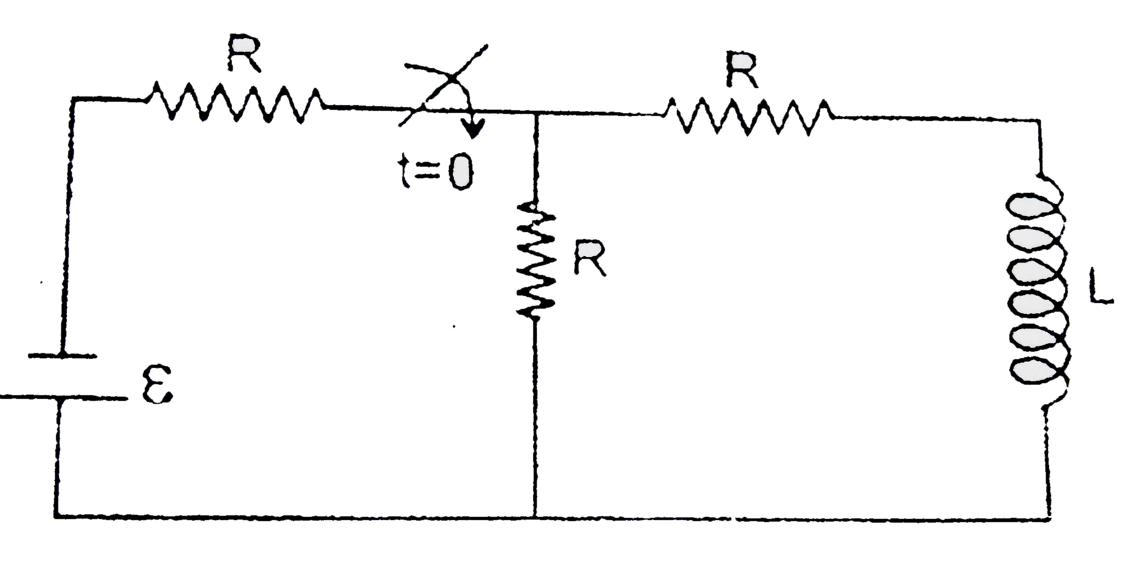
View SolutionIn the following circuit (Fig.)the switch is closed at t=0. Intially, there is no current in inductor. Find out the equation of current in the inductor coil as s function of time.
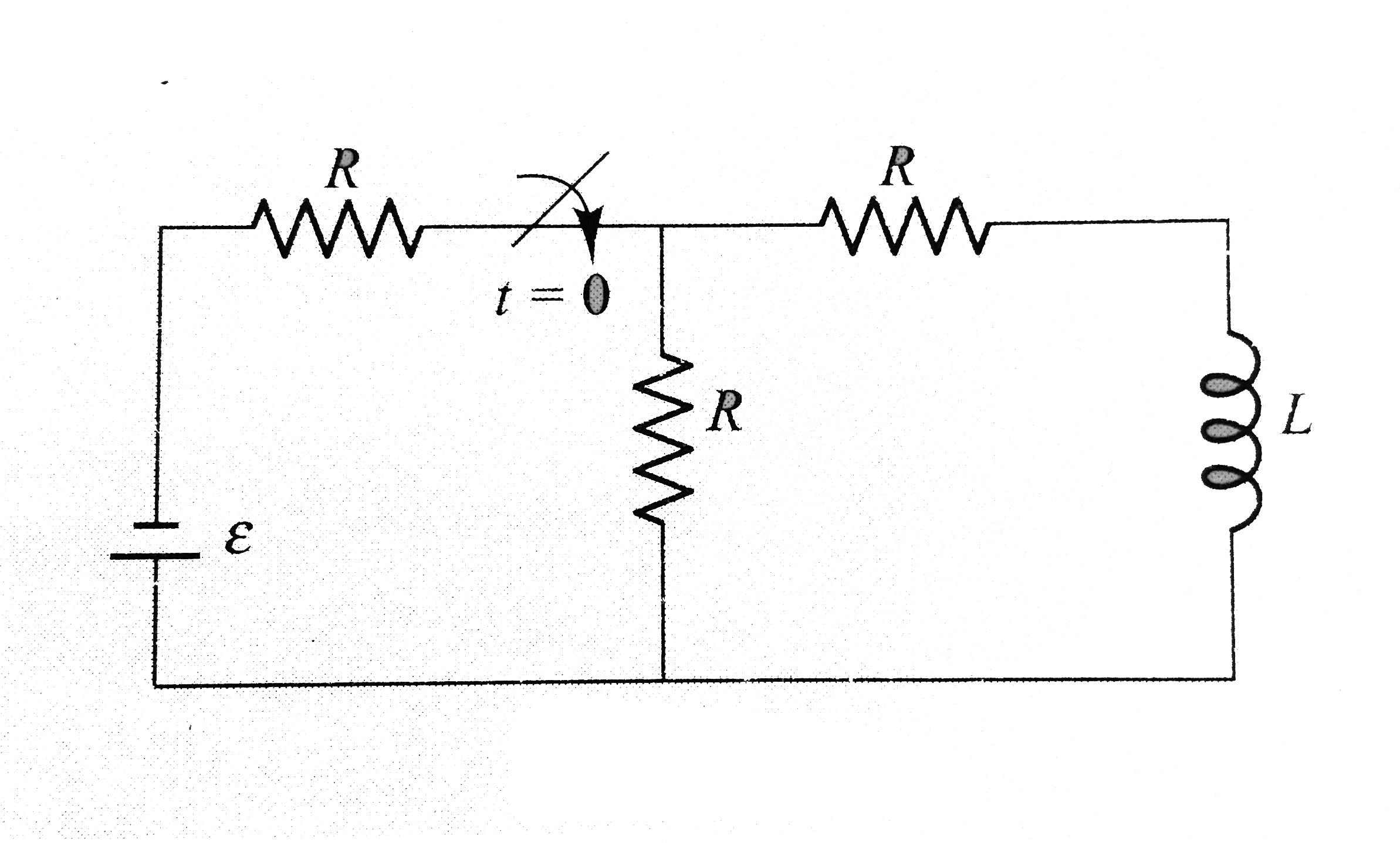
View SolutionA circuit contains an ideal cell and an inductor with a switch. Initially, the switch is open. It is closed at t=0. Find the current as a function of time.
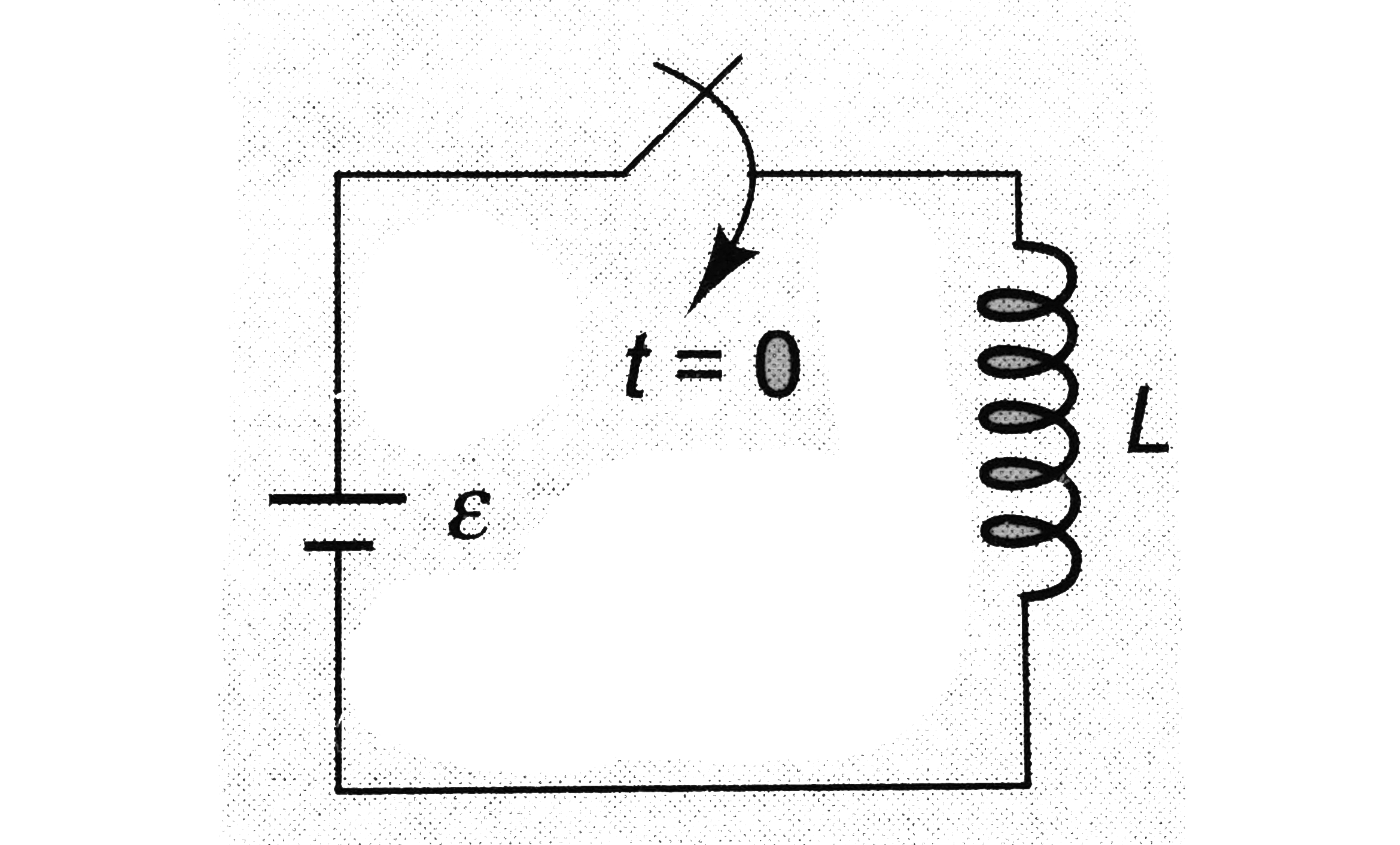
View SolutionA circuit contains an ideal cell and an inductor with a switch. Initially, the switch is open. It is closed at t=0. Find the current as a function of time.

View SolutionIn the circuit shown, switch S is closed at time t=0. Find the current through the inductor as a function of time t.
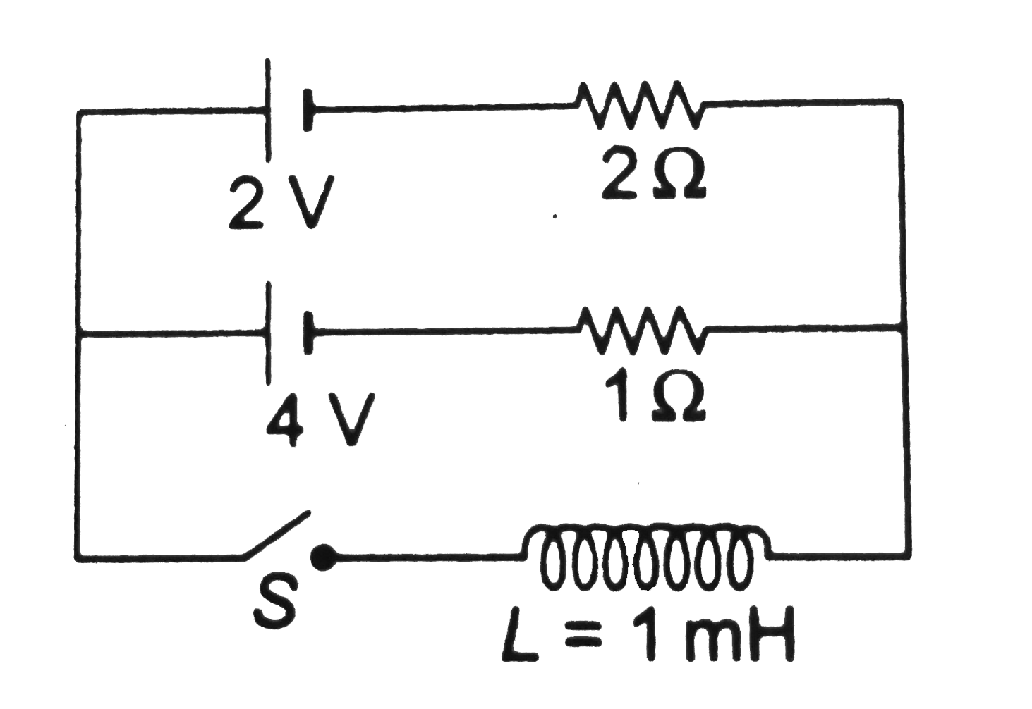
View SolutionFigure below shows a capacitor C, an inductor L and a resistor R, connected in series to an a.c. supply of 220 V.
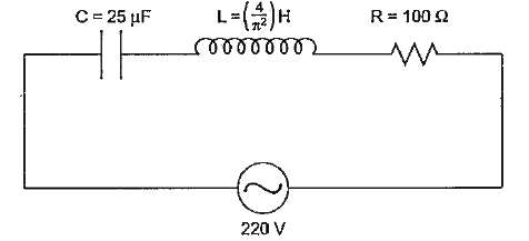
Current flowing through the circuit.
View Solution