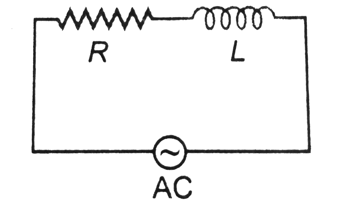
Explain the term 'inductive reactance'.Show graphically the variation of inductive reactance with frequency of the applied alternating voltage.
An a.c. voltage E=E0sinωt is applied across a pure inductor L.Show mathematically that the current flowing through it lags behind the applied voltage by a phase angle of π/2.
Step-by-Step Solution
Step 1: Define Inductive Reactance
Inductive reactance (denoted as XL) is a measure of the opposition that an inductor presents to the flow of alternating current (AC). It is given by the formula:
XL=2πfL
where:
- XL is the inductive reactance in ohms (Ω),
- f is the frequency of the AC voltage in hertz (Hz),
- L is the inductance of the inductor in henries (H).
Step 2: Graphical Representation of Inductive Reactance
To graph the variation of inductive reactance with frequency, we can plot XL on the y-axis and frequency f on the x-axis. Since XL is directly proportional to f, the graph will be a straight line passing through the origin with a slope of 2πL.
- Graph Description: The graph will start at the origin (0,0) and increase linearly. The slope of the line is 2πL, indicating that as frequency increases, inductive reactance increases.
Step 3: Analyze the AC Voltage Across a Pure Inductor
Given the AC voltage:
E=E0sin(ωt)
where:
- E0 is the maximum voltage,
- ω is the angular frequency (ω=2πf).
Step 4: Relate Voltage and Current in the Inductor
The voltage across an inductor is related to the current through it by the equation:
V=Ldidt
Substituting the expression for voltage:
E0sin(ωt)=Ldidt
Step 5: Integrate to Find Current
Rearranging the equation gives:
didt=E0Lsin(ωt)
Integrating both sides with respect to time t:
i(t)=∫E0Lsin(ωt)dt
The integral of sin(ωt) is:
−E0Lωcos(ωt)+C
Assuming the constant of integration C=0 (as the current is zero at t=0), we have:
i(t)=−E0Lωcos(ωt)
Step 6: Express Current in Sine Form
Using the identity cos(θ)=sin(θ+π2):
i(t)=E0Lωsin(ωt−π2)
Letting I0=E0Lω, we can write:
i(t)=I0sin(ωt−π2)
Step 7: Conclusion on Phase Difference
From the expression i(t)=I0sin(ωt−π2), we see that the current i(t) lags behind the voltage E(t) by a phase angle of π2 radians.
Summary
1. Inductive Reactance: XL=2πfL
2. Graph: Linear increase of XL with frequency f.
3. Phase Difference: Current lags voltage by π2.
- XL is the inductive reactance in ohms (Ω),
- f is the frequency of the AC voltage in hertz (Hz),
- L is the inductance of the inductor in henries (H).
- E0 is the maximum voltage,
- ω is the angular frequency (ω=2πf).
2. Graph: Linear increase of XL with frequency f.
3. Phase Difference: Current lags voltage by π2.
Topper's Solved these Questions
- ALTERNATING CURRENTBook:RESONANCE ENGLISHChapter:ALTERNATING CURRENTExercise:A.L.P
Explore 10 Videos
- ALTERNATING CURRENTBook:RESONANCE ENGLISHChapter:ALTERNATING CURRENTExercise:EXAMPLE
Explore 40 Videos
- ALTERNATING CURRENTBook:RESONANCE ENGLISHChapter:ALTERNATING CURRENTExercise:Exercise -3 Part-2
Explore 3 Videos
- ATOMIC PHYSICSBook:RESONANCE ENGLISHChapter:ATOMIC PHYSICSExercise:Advanved level problems
Explore 17 Videos
Similar Questions
Explain the term 'capacitive reactance'.Show graphically the variation of capacitive reactance with frequency of the applied alternating voltage.
An a.c. voltage E=E0sinωt is applied a across a pure capacitor C.Show mathematically that the current flowing through it leads the applied voltage by a phase angle of π/2
View SolutionAn alternating voltage E=E0sinωt , is applied across a coil of inductor L. The current flowing through the circuit at any instant is
View SolutionA small signal voltage V(t)=V0sinωt is applied across an ideal capacitor C:
View SolutionProve that the current flowing through an ideal inductor connected across a.c. source, lags the voltage in phase by π2.
View Solution(a) Draw graphs showing the variations of inductive reactnace and capacitive reactance with frequency of the applied ac source .
(b) Draw the phasor diagram for a series RC circuit connected to an ac source.
(c ) An alternating voltage of 220 V is applied across a device X , a current of 0.25 A flows , which lag behind the applied voltage in phase by π2 radian . If the same voltage is applied across another device Y , the same current flows but now it is in phase with the applied voltage .
(i) Name the devices X and Y.
(ii) Calculate the current flowing in the circuit when the same voltage is applied across the series combination of X and Y.

View SolutionIn an LR-circuit, the inductive reactance is equal to the resistance R of the circuit. An e.m.f E=E0cos(ωt) applied to the circuit. The power consumed in the circuit is
View SolutionAn alternating voltage given by
E=280sin50πt is connected across a pure resistor of 40 ohm. Find frequency of source and rms current through the bulb.
View SolutionA circuit contains resistance R and an inductance L in series. An alternating voltage V=V0sinωt is applied across it. The currents in R and L respectively will be
 .
.
View SolutionA circuit contains resistance R and an inductance L in series. An alternating voltage V=V0sinωt is applied across it. The currents in R and L respectively will be
 .
.
View SolutionAn alternating voltage is connected in series with a resistance R and inductance L if the potential drop across the resistance is 200V and across the inductance is 150V, then the applied voltage is
View Solution
