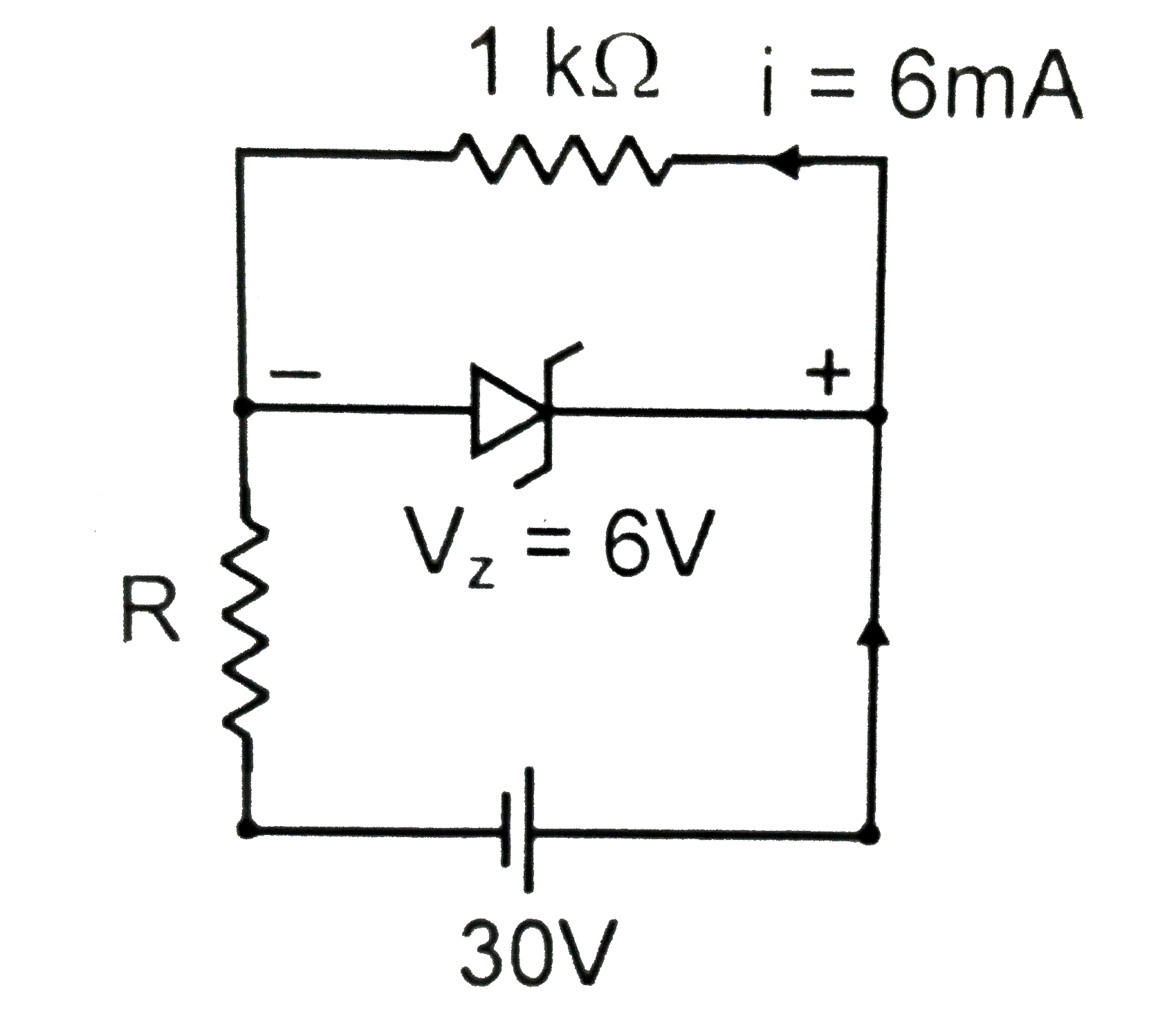
A zener diode of voltage volt) is used to maintain a constant voltage across a load resistance by using a series resistance . If the emf or source is , clculate the value of current through series resistance, zener diode and load resistance. What is the power being dissipated in zener diode.
To solve the problem, we need to calculate the current through the series resistance, the Zener diode, and the load resistance, as well as the power dissipated in the Zener diode. Let's break it down step by step.
Step 1: Identify the given values
- Zener voltage, VZ=6V
- Load resistance, RL=1000Ω
- Series resistance, RS=100Ω
- Source voltage, E=9V
Step 2: Calculate the voltage across the series resistance
The total voltage supplied by the source is 9V. The Zener diode maintains a constant voltage of 6V across the load resistance. Therefore, the voltage across the series resistance VS can be calculated as:
VS=E−VZ=9V−6V=3V
Step 3: Calculate the current through the series resistance
Using Ohm's Law, the current IS through the series resistance can be calculated as:
IS=VSRS=3V100Ω=0.03A
Step 4: Calculate the current through the load resistance
The voltage across the load resistance is the same as the Zener voltage, which is 6V. Therefore, the current IL through the load resistance can be calculated as:
IL=VZRL=6V1000Ω=0.006A
Step 5: Calculate the current through the Zener diode
The current through the Zener diode IZ can be found by subtracting the load current from the series current:
IZ=IS−IL=0.03A−0.006A=0.024A
Step 6: Calculate the power dissipated in the Zener diode
The power PZ dissipated in the Zener diode can be calculated using the formula:
PZ=VZ×IZ=6V×0.024A=0.144W
Summary of Results
- Current through series resistance, IS=0.03A
- Current through load resistance, IL=0.006A
- Current through Zener diode, IZ=0.024A
- Power dissipated in Zener diode, PZ=0.144W
- Zener voltage, VZ=6V
- Load resistance, RL=1000Ω
- Series resistance, RS=100Ω
- Source voltage, E=9V
The total voltage supplied by the source is 9V. The Zener diode maintains a constant voltage of 6V across the load resistance. Therefore, the voltage across the series resistance VS can be calculated as:
VS=E−VZ=9V−6V=3V
Using Ohm's Law, the current IS through the series resistance can be calculated as:
IS=VSRS=3V100Ω=0.03A
The voltage across the load resistance is the same as the Zener voltage, which is 6V. Therefore, the current IL through the load resistance can be calculated as:
IL=VZRL=6V1000Ω=0.006A
The current through the Zener diode IZ can be found by subtracting the load current from the series current:
IZ=IS−IL=0.03A−0.006A=0.024A
The power PZ dissipated in the Zener diode can be calculated using the formula:
PZ=VZ×IZ=6V×0.024A=0.144W
- Current through series resistance, IS=0.03A
- Current through load resistance, IL=0.006A
- Current through Zener diode, IZ=0.024A
- Power dissipated in Zener diode, PZ=0.144W
Topper's Solved these Questions
- SEMICONDUCTORSBook:RESONANCE ENGLISHChapter:SEMICONDUCTORSExercise:Exercise
Explore 100 Videos
- SEMICONDUCTORSBook:RESONANCE ENGLISHChapter:SEMICONDUCTORSExercise:Exercise 2
Explore 16 Videos
- REVISION DPPBook:RESONANCE ENGLISHChapter:REVISION DPPExercise:All Questions
Explore 463 Videos
- SIMPLE HARMONIC MOTION Book:RESONANCE ENGLISHChapter:SIMPLE HARMONIC MOTION Exercise:Advanced Level Problems
Explore 13 Videos
Similar Questions
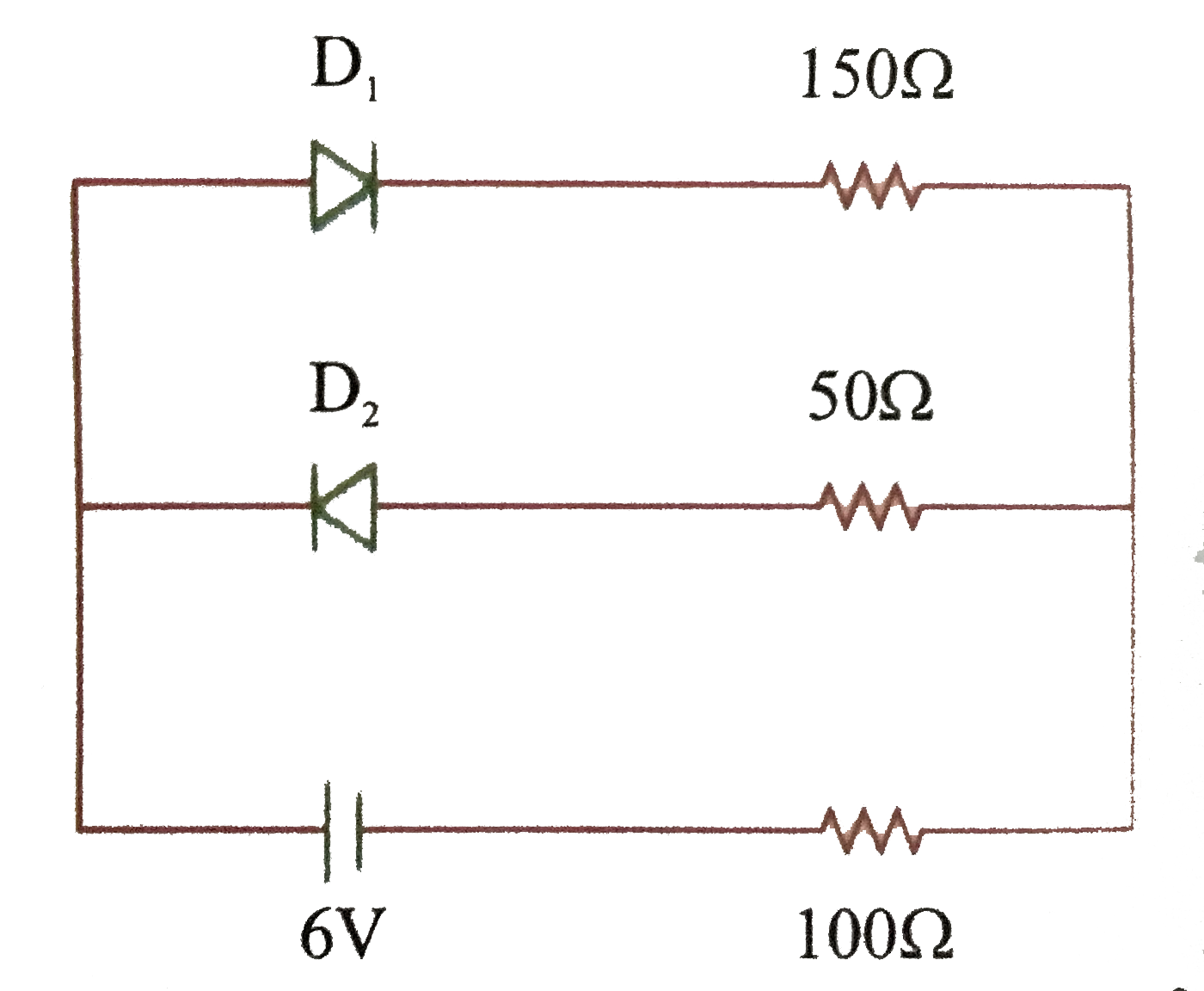
The circuit shown in the figure contains two diodes each with a forward resistance of 50Ω and with infinite backward resistance. If the batter of 6 V is connected in the circuit, then the current through the 100Ω resistance is
View SolutionThe circuit shown in figure (1) Contains two diodes each with a forward resistance of 50ohm and with infinite reverse resistance. If the battery voltage is 6V, the current through the 100ohm resistance is.
 .
.
View Solution
Knowledge Check
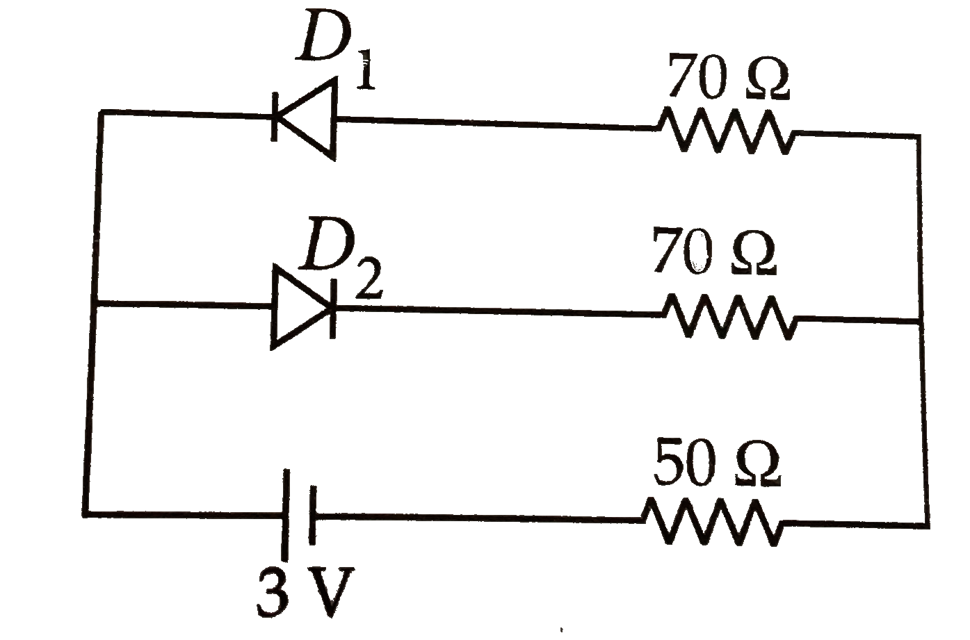
The circuit shown in the figure contains two diodes each with a forward resistance of 30 Ω and with infinite backward resistance. If the battery is 3 V, the current through the 50 Ω resistance (in ampere) is
 AzeroB0.01C0.02D0.03
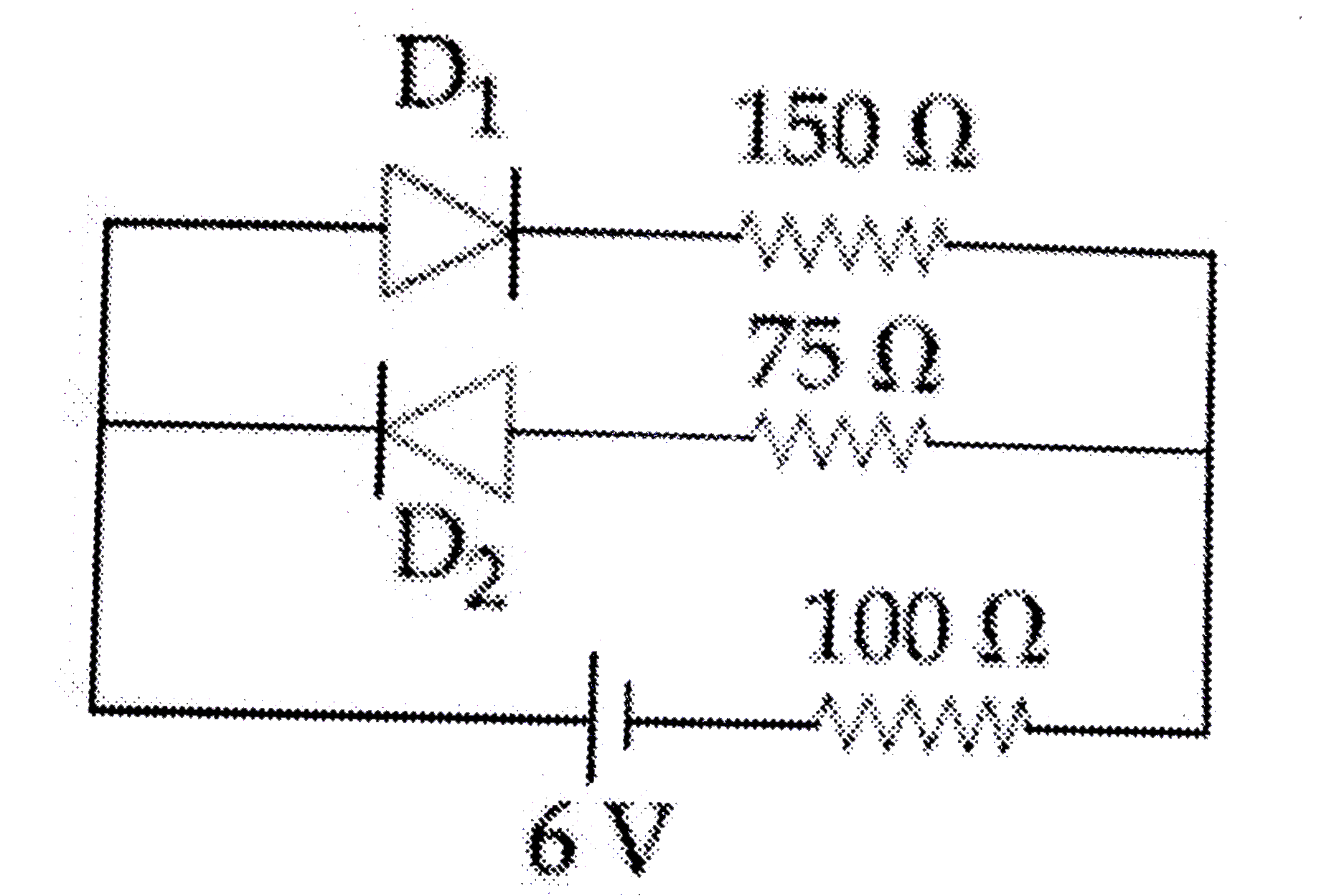
The circuit showm below contains two ideal diodes, each with a forward resistance of 50Ω. If the battery voltage is 6 V, the current through the 100Ω resistance ( in Amperes) is:

View SolutionThe circuit shown in figure contains two diodes each with a forward resistance of 50Ω and infinite reverse resistance.If the battery voltage is 6 v ,then the current through the 100Ω resistance is
View SolutionIf voltage across zener diode is 6V then find out value of maximum resistance in this condition.

View SolutionIn input in a full - wave rectifier is e=50sin(314t) volt, diode resistance is 100Ω and load resistance is 1kΩ then, pulse frequency of output voltage is
View SolutionAn rms voltage of 110 V is applied across a series circuit having a resistance 11Ω and an impedance 22Ω. The power consumed is
View SolutionA battery of EMF 10 V, with internal resistance 1Ω is being charged by a 120 V d.c. supply using a series resistance of 10Ω. The terminal voltage of the battery is
View SolutionWhen a resistance of 100Ω is connected in series with a galvanometer of resistance R, then its range is V. To double its range, a resistance of 1000Ω is connected in series. Find the value of R.
View Solution