A 200Ω resistor and 1H inductor are joined in series with an ac source of emf 10√2sin(200t)V. Calculate the phases difference between emf and current.
To solve the problem of finding the phase difference between the EMF and the current in a series circuit consisting of a resistor and an inductor, we can follow these steps:
1. Identify the given values:
- Resistance, R=200Ω
- Inductance, L=1H
- EMF, E(t)=10√2sin(200t)
2. Determine the angular frequency (ω):
- The EMF can be compared to the standard form E(t)=E0sin(ωt).
- From the equation, we can see that ω=200rad/s.
3. Calculate the inductive reactance (XL):
- The inductive reactance is given by the formula:
XL=ωL
- Substituting the values:
XL=200×1=200Ω
4. Determine the capacitive reactance (XC):
- Since there is no capacitor in the circuit, XC=0.
5. Calculate the phase difference (ϕ):
- The phase difference tanϕ is given by:
tanϕ=XC−XLR
- Substituting the values:
tanϕ=0−200200=−1
6. Find the angle ϕ:
- To find ϕ, we take the arctangent:
ϕ=tan−1(−1)
- This gives:
ϕ=−π4radians
7. Interpret the result:
- The negative sign indicates that the current lags behind the EMF by π4 radians.
Final Answer:
The phase difference between the EMF and the current is π4 radians, with the current lagging behind the EMF.
---
- Resistance, R=200Ω
- Inductance, L=1H
- EMF, E(t)=10√2sin(200t)
- The EMF can be compared to the standard form E(t)=E0sin(ωt).
- From the equation, we can see that ω=200rad/s.
- The inductive reactance is given by the formula:
XL=ωL
- Substituting the values:
XL=200×1=200Ω
- Since there is no capacitor in the circuit, XC=0.
- The phase difference tanϕ is given by:
tanϕ=XC−XLR
- Substituting the values:
tanϕ=0−200200=−1
- To find ϕ, we take the arctangent:
ϕ=tan−1(−1)
- This gives:
ϕ=−π4radians
- The negative sign indicates that the current lags behind the EMF by π4 radians.
The phase difference between the EMF and the current is π4 radians, with the current lagging behind the EMF.
Topper's Solved these Questions
- ALTERNATING CURRENTBOOK - CENGAGE PHYSICS ENGLISHCHAPTER - ALTERNATING CURRENTEXERCISE - Solved Examples
6 Videos
- ALTERNATING CURRENTBOOK - CENGAGE PHYSICS ENGLISHCHAPTER - ALTERNATING CURRENTEXERCISE - Exercise 5.1
15 Videos
- ATOMIC PHYSICSBOOK - CENGAGE PHYSICS ENGLISHCHAPTER - ATOMIC PHYSICSEXERCISE - ddp.4.3
15 Videos
Similar Questions
A 12 Ω resistor and a 0.21 H inductor are connected in series to an a.c. source operating at V, 50 cycle second. The phase angle between current and source vottage is
View SolutionA 12 Ω resistor and a 0.21 H inductor are connected in series to an a.c. source operating at V, 50 cycle second. The phase angle between current and source vottage is
View SolutionA coil of resistance 200 ohms and self inductance 1.0 henry has been connected in series to an a.c. source of frequency 200πHz. The phase difference between voltage and current is
View SolutionA capacitor, a resistor and a 40 mH inductor are connected in series to an a.c. source of frequency 60 Hz. Calculate the capacitance of the capacitor,if current is in phase with the voltage.
View SolutionAnswer the following:
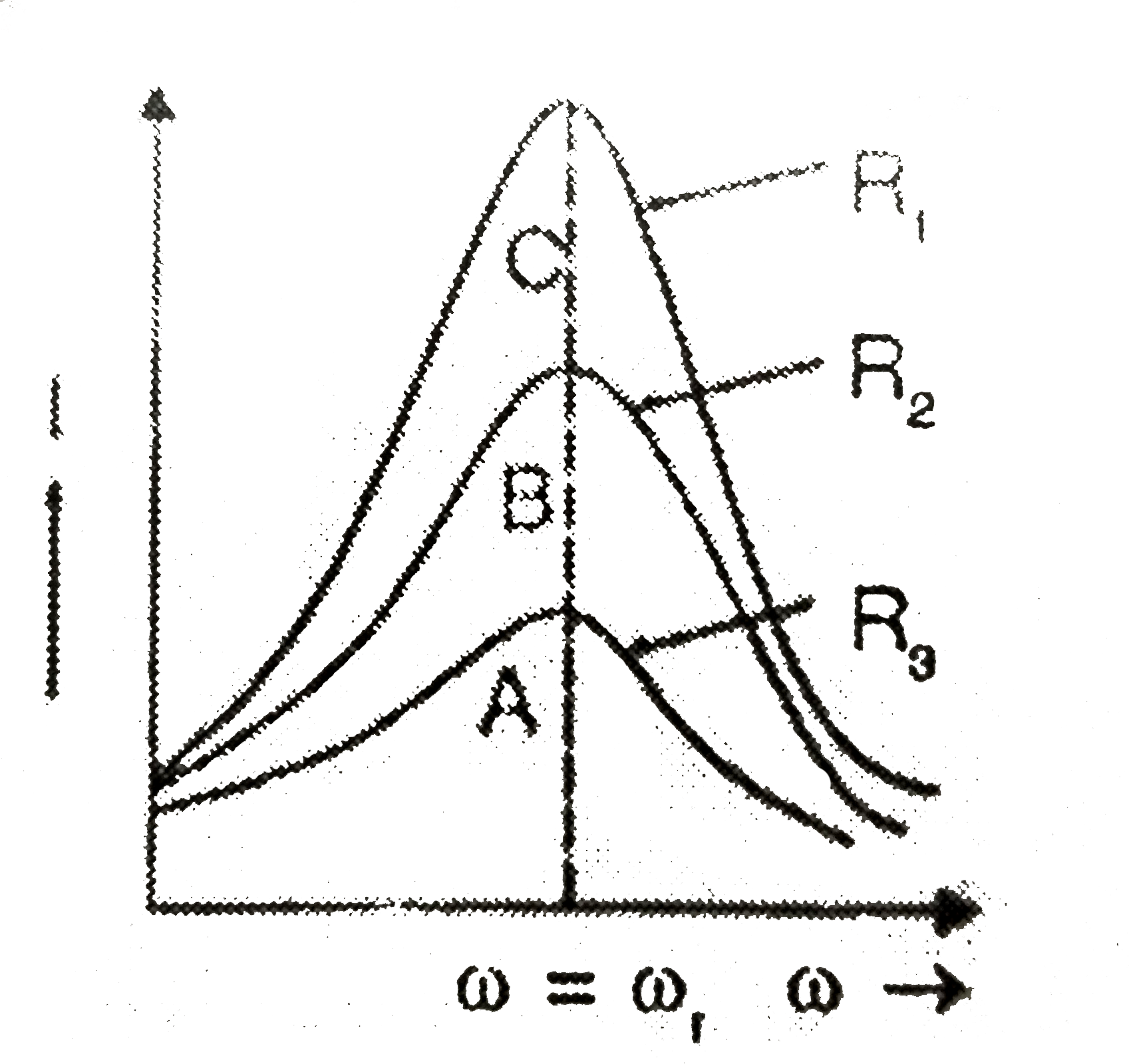
(a) What do you understand by 'sharpness of resonance' for a series LCR resonant circuit? How is it related with the quality factor 'Q' of the circuit? Using the graphs given in the diagram, explain the factors which affect it. For which graph is the resistance (R ) minimum?
(b) A 2μF capacitor, 100Ω resistor and 8H inductor are connected in series with an ac source. Find the frequency of the ac source for which the current drawn in the circuit is maximum.
If the peak value of emf of the source is 200 V, calculate the (i) maximum current, and (ii) inductive and capacitive reactance of the circuit at resonance.

View SolutionThere is a 5Ω resistance in an AC, circuit. Inductance of 0.1H is connected with it in series. If equation of AC emf is 5sin50t then the phase difference between current and e.m.f. is
View SolutionA 25(μ)F capacitor, a 0.1 H inductor and a 25Ω resistor are connected in series with an ac source of emf E=310sin314t. Find
(a) the frequency of the emf
(b) the impedance of the circuit
(c) the current in the circuit.
(d) the phase angle
View SolutionA 50μF capacitor, a 30Ω esistor and a 0.7 H inductor are connected in series to an a.c. supply which generates an emf .e. given by e = 300 sin (200 t) volt. Calculate peak value of the current flowing through the circuit.
View SolutionA 0.01 H inductor and √3πΩ resistance are connected in series with a 220 V, 50 Hz AC source. The phase difference between the current and emf is
View SolutionA 9/100(π) inductor and a 12Ω resistanace are connected in series to a 225 V, 50 Hz ac source. Calculate the current in the circuit and the phase angle between the current and the source voltage.
View Solution
