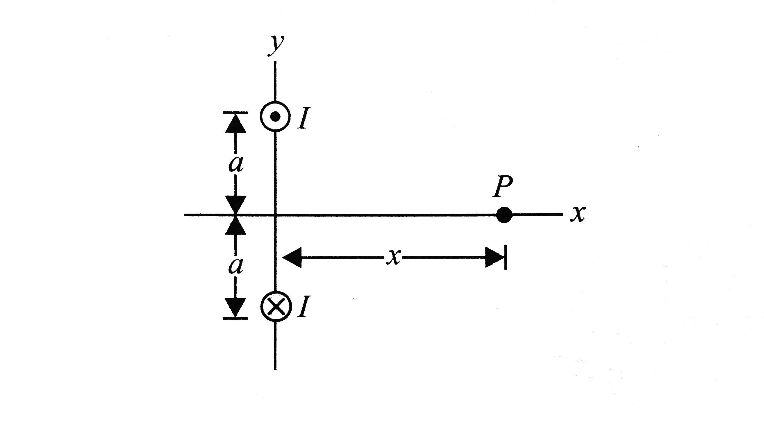
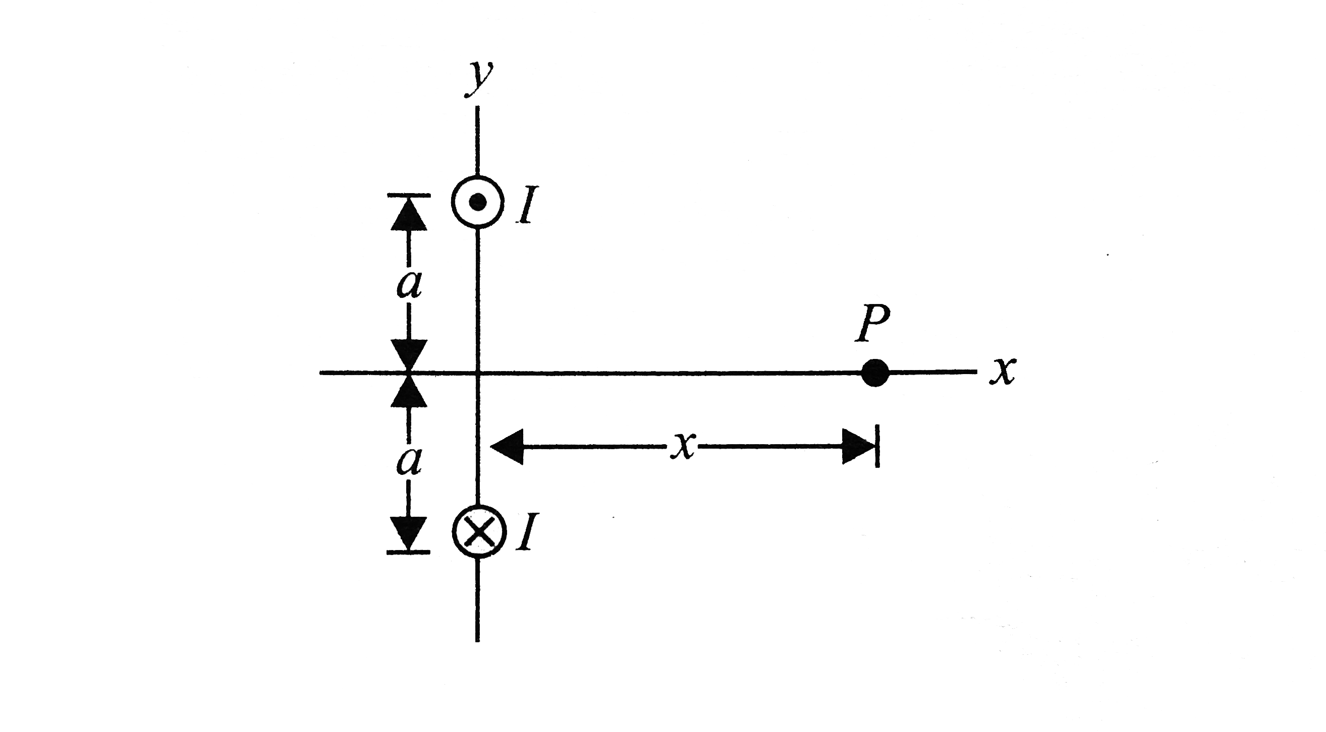
Repeat the above problem, but with the current in both wires shown in fig. directed into the plane of the figure.
Graph the magnitude of at points on the x-axis.
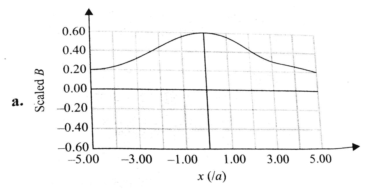
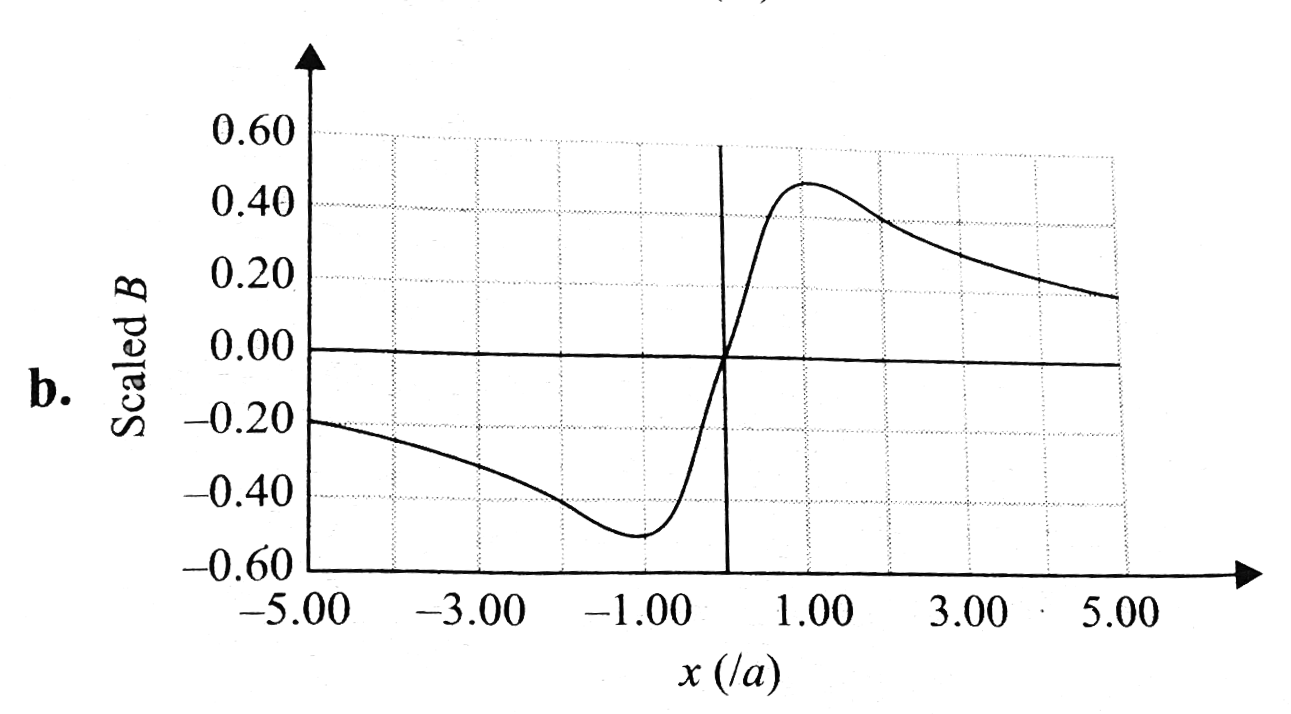
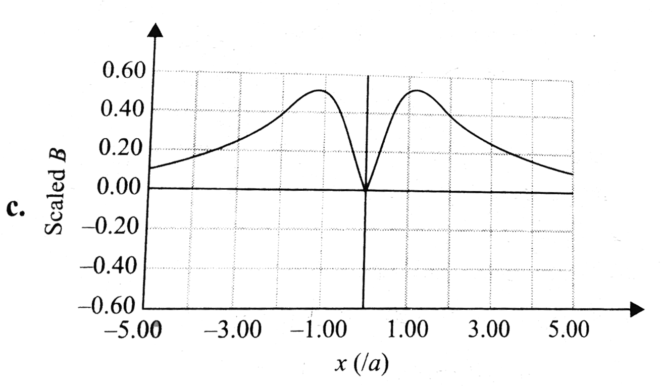
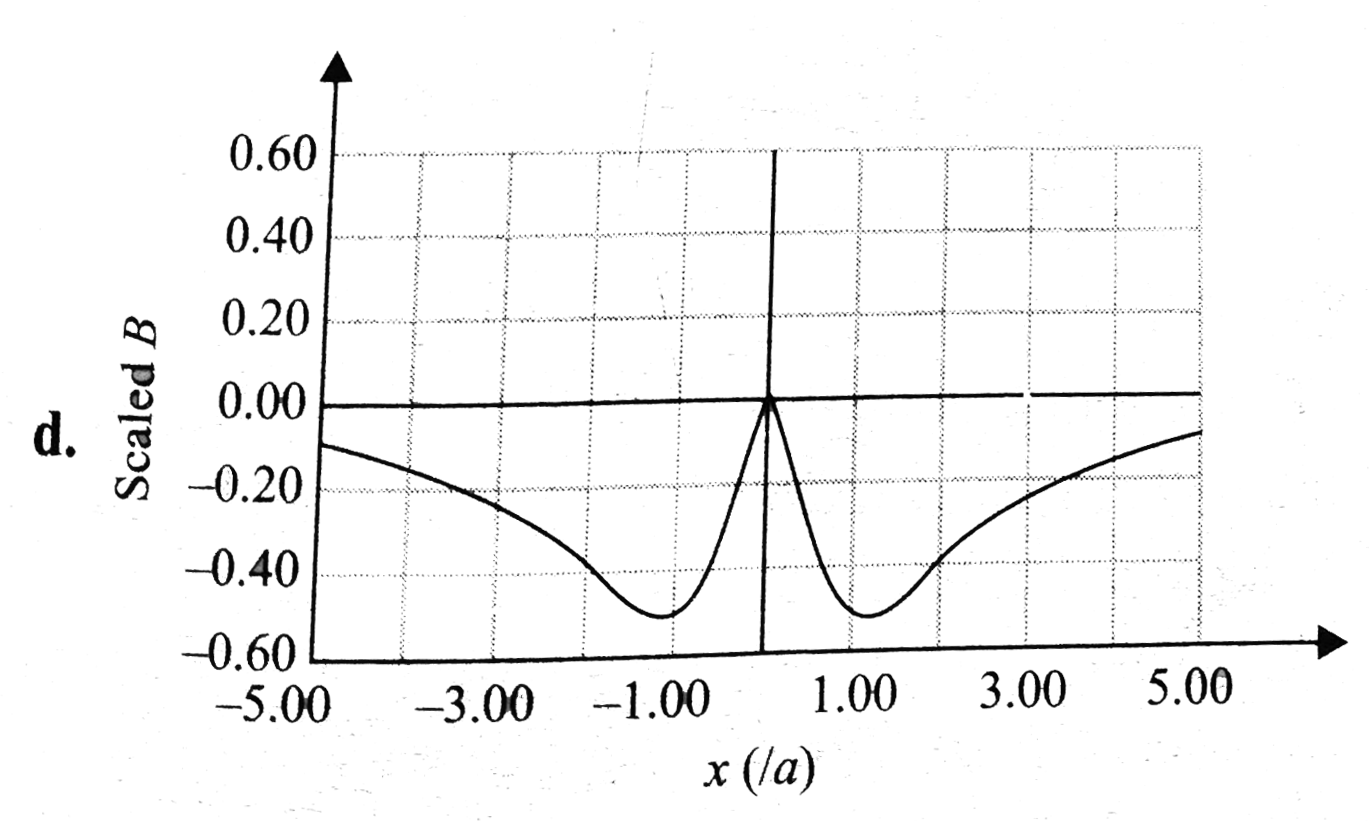
The correct Answer is:B
To solve the problem of finding the magnetic field →B at points on the x-axis due to two parallel wires carrying current into the plane of the figure, we can follow these steps:
Step 1: Understand the Configuration
We have two long straight wires, both carrying currents I into the plane of the paper. Let’s denote the distance of each wire from the origin as A. The wires are positioned symmetrically about the origin on the y-axis.
Step 2: Determine the Magnetic Field Contribution from Each Wire
Using the right-hand rule for magnetic fields around a current-carrying wire, the magnetic field →B at a point on the x-axis due to a single wire is given by:
B=μ0I2πr
where r is the distance from the wire to the point where we are calculating the magnetic field.
Step 3: Calculate the Magnetic Field at a Point on the x-axis
Let’s consider a point P on the x-axis at a distance x from the origin. The distances from the two wires to point P will be:
- From the wire at y=A: r1=√x2+A2
- From the wire at y=−A: r2=√x2+A2
Since both currents are directed into the plane, the magnetic fields at point P due to both wires will be in opposite directions. Therefore, the total magnetic field B at point P is:
B=B1−B2=μ0I2πr1−μ0I2πr2
Since r1=r2, we can simplify this to:
B=0
at the point directly on the x-axis when x=0.
Step 4: Analyze the Behavior of the Magnetic Field as x Changes
1. At x=0: The magnetic field B=0.
2. As x→∞: The distance r becomes very large, and thus:
B→0
3. At x=A: We can substitute x=A into the magnetic field equation:
B=μ0I2πA−μ0I2πA=0
4. At x=−A: Similarly, we find:
B=0
Step 5: Determine the Maximum Value of B
To find the maximum value of B, we can differentiate the expression for B with respect to x and set it to zero. This will give us the points where B could be maximized.
Step 6: Graph the Magnitude of B
The graph of the magnetic field B as a function of x will show:
- B=0 at x=0
- B will reach a maximum value at x=A and x=−A
- B→0 as x→∞ or x→−∞
Conclusion
The graph will show a symmetrical behavior around the origin, with peaks at x=A and x=−A, and it will touch the x-axis at x=0 and as x→±∞.
---
We have two long straight wires, both carrying currents I into the plane of the paper. Let’s denote the distance of each wire from the origin as A. The wires are positioned symmetrically about the origin on the y-axis.
Using the right-hand rule for magnetic fields around a current-carrying wire, the magnetic field →B at a point on the x-axis due to a single wire is given by:
B=μ0I2πr
where r is the distance from the wire to the point where we are calculating the magnetic field.
Let’s consider a point P on the x-axis at a distance x from the origin. The distances from the two wires to point P will be:
- From the wire at y=A: r1=√x2+A2
- From the wire at y=−A: r2=√x2+A2
B=B1−B2=μ0I2πr1−μ0I2πr2
Since r1=r2, we can simplify this to:
B=0
at the point directly on the x-axis when x=0.
1. At x=0: The magnetic field B=0.
2. As x→∞: The distance r becomes very large, and thus:
B→0
3. At x=A: We can substitute x=A into the magnetic field equation:
B=μ0I2πA−μ0I2πA=0
4. At x=−A: Similarly, we find:
B=0
To find the maximum value of B, we can differentiate the expression for B with respect to x and set it to zero. This will give us the points where B could be maximized.
The graph of the magnetic field B as a function of x will show:
- B=0 at x=0
- B will reach a maximum value at x=A and x=−A
- B→0 as x→∞ or x→−∞
The graph will show a symmetrical behavior around the origin, with peaks at x=A and x=−A, and it will touch the x-axis at x=0 and as x→±∞.
Topper's Solved these Questions
- SOURCES OF MAGNETIC FIELDBOOK - CENGAGE PHYSICS ENGLISHCHAPTER - SOURCES OF MAGNETIC FIELDEXERCISE - Exercise (integer)
7 Videos
- SOURCES OF MAGNETIC FIELDBOOK - CENGAGE PHYSICS ENGLISHCHAPTER - SOURCES OF MAGNETIC FIELDEXERCISE - Archives (fill In The Blanks)
1 Videos
- SOURCES OF MAGNETIC FIELDBOOK - CENGAGE PHYSICS ENGLISHCHAPTER - SOURCES OF MAGNETIC FIELDEXERCISE - Exercise (assertion-reasioning )
2 Videos
- RAY OPTICSBOOK - CENGAGE PHYSICS ENGLISHCHAPTER - RAY OPTICSEXERCISE - DPP 1.6
12 Videos
- WAVE OPTICSBOOK - CENGAGE PHYSICS ENGLISHCHAPTER - WAVE OPTICSEXERCISE - Comprehension Type
14 Videos
Similar Questions
Repeat the above problem, but with the current in both wires shown in fig. directed into the plane of the figure.
At what value of x is the magnitude of →B is maximum?
View SolutionRepeat the above problem, but with the current in both wires shown in fig. directed into the plane of the figure.
Derive the expression for the magnitude of →B at any point on the x-axis in terms of the x-coordinate of the point. What is the direciton of →B?
View SolutionFigure shows an end view of two long, parallel wires perpendicular to the xy plane, each carrying a current I, but in opposite directions.
Graph the magnitude of →B at point on the x-axis.
View SolutionFigure shows an end view of two long, parallel wires perpendicular to the xy plane, each carrying a current I, but in opposite directions.
Derive an expression for the magnitude of →B at any point on the x-axis in terms of the x-coordinate of the point. What is the direction of →B?
View Solutiona straight wire current element is carrying current 100 A as shown in figure. the magnitude of magnetic field at a point P.

View SolutionA wire carrying current i is bent as shown in figure and placed in the plane of uniform magnetic field Bvec. The magnitude of magnetic force experienced by
View SolutionA conducting wire carrying current I is shown in the figure. The magnitude of magnetic field at the point P will be

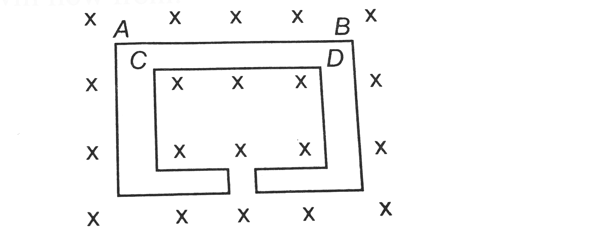
View SolutionA wire is bent to form the double loop shown in figure. There is a uniform magnetic field directed into the plane of the loop. If the magnitude of this field is decreasing current will flow from:
View SolutionTwo straight infinitely long current carrying wires are kept along Z-axis at the coordinates (0,a,0) and (0, -a, 0) respectively, as shown in the figure. The current in each of the wire is equal and along negative Z-axis (into the plane of the paper).
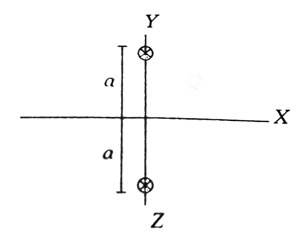
The variation of magnetic field on the X-axis will be approximately
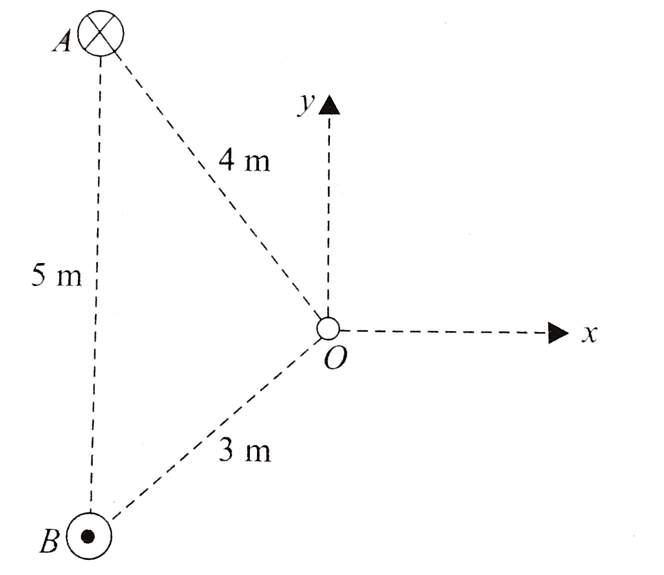
View SolutionTwo infinitely long straight parallel wire are 5 m apart, perpendicular to the plane of paper. One of the wires, as it passes perpendicular to the plane of paper, intersects it at A and carries current I in the downward direction. The other wire intersects the plane of paper at point B and carries current k int the outward direction O in the plane of paper as shown in Fig. With x and y axis shown, magnetic induction at O in the component form can be expressed as
View Solution
