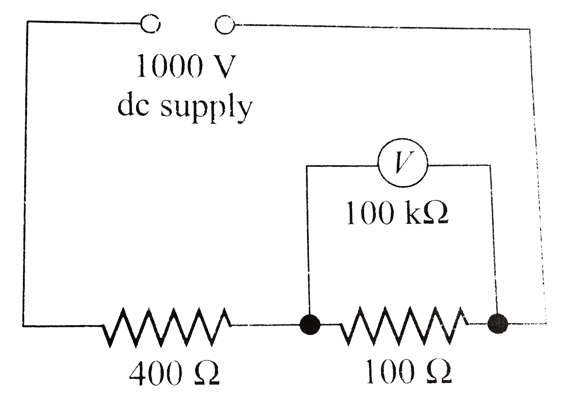
A constant voltage dc source is connected, as shown in Fig. A2.7, across two resistors of resistances 400kΩ and 100kΩ. What is the reading of the voltmeter, also of resistance 100kΩ, when connected across the second resistor as shown?
111 V
250 V
125 V
333 V
The correct Answer is:A
a. Effective resistance across voltmeter is 50kΩ. Total resistance
across the dc supply is 450kΩ.
Current drawn from supply 1000V/450kΩ=1/450A. Potential difference across voltmeter is
50×1000450V=10009V=111V .
Similar Questions
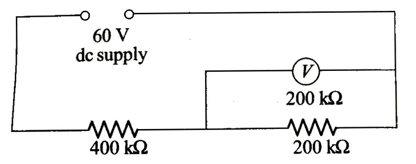
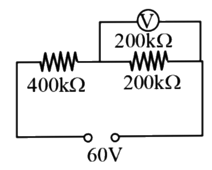
A constant 60V dc supply is connected across two resistors of resistance 400kΩ and 200kΩ. What is the reading of the voltmeter, also of resistance 200kΩ, when connected across the second resistor as shows in Fig. 6.48?
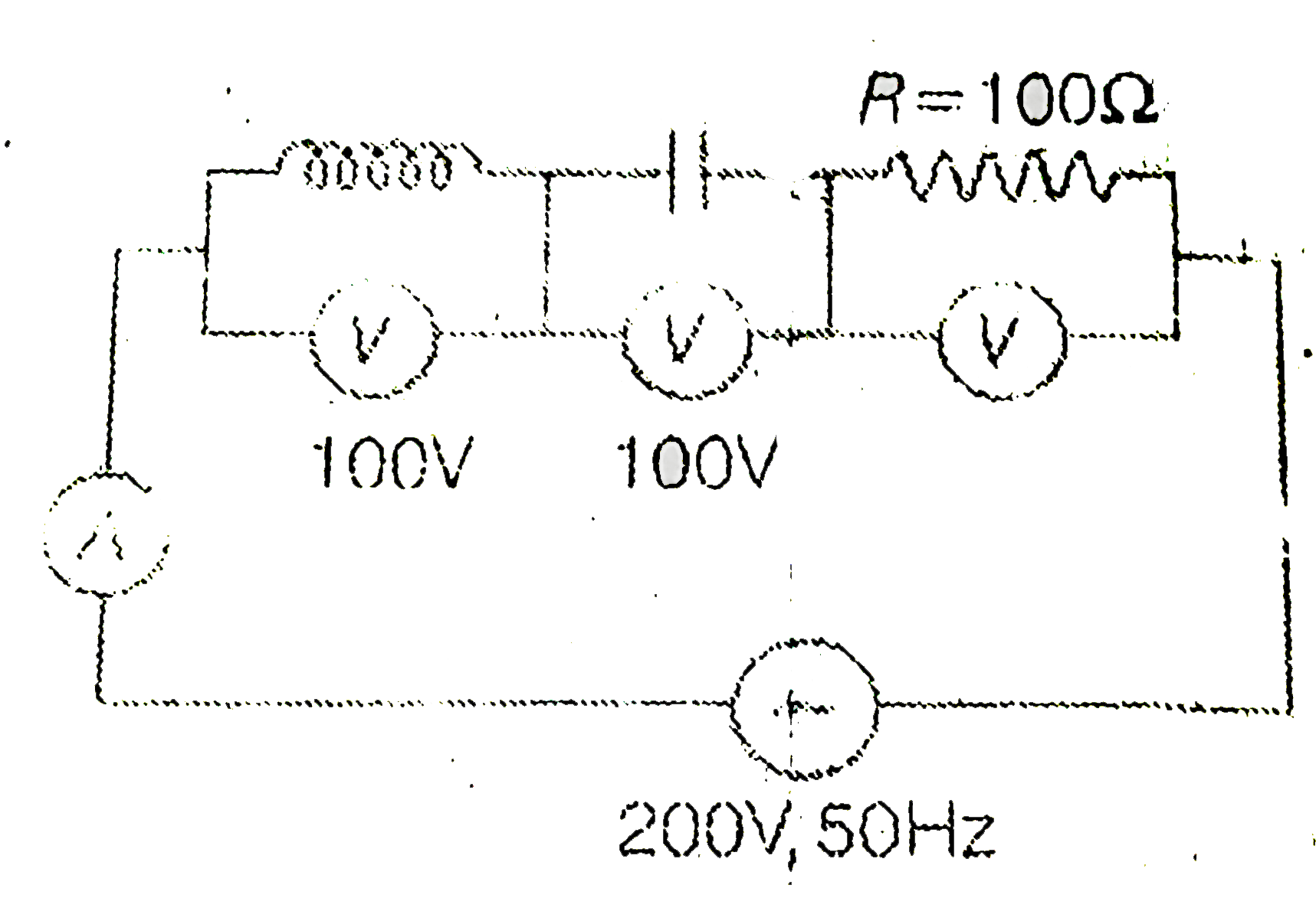
View SolutionWhat will be the reading if the voltmeter across in resistance and ammetere in the cirucit shown in the figure?
View Solution
Knowledge Check
7 V battery with internal resistance 2Ωand3V battery with internal resistance 1Ω are connected to a 10Ω resistors as shown in figure, the current in 10Ω resistor is
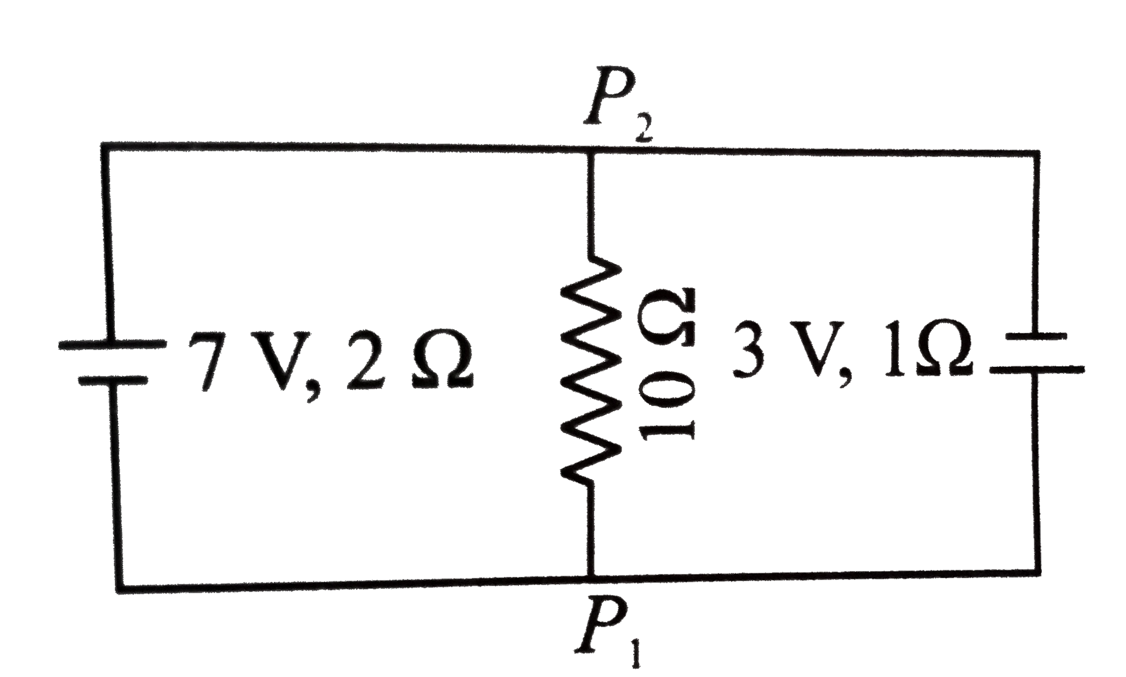 A0.27AB0.31AC0.031AD0.53
A constant 60 V supply is connected across the two resistors as shown in diagram. Calculate the reading of the voltmeter which has a resistance of 200 KΩ
View SolutionTwo resistor 400Ω and 800Ω connected in series across a 6 V battery . Reading of Voltmeter of 10kΩ across 400Ω resistor is close to :
View SolutionThe values of two resistors are R1=(6±0.3)kΩ and R2=(10±0.2)kΩ. The percentage error in the equivalent resistance when they are connected in parallel is
View SolutionIn the circuit shows in Fig. 6.42, resistors X and Y, each with resistance R, are connected to a 6V battery of negligible internal resistance. A voltmeter, also of resistance R, is connected across Y.
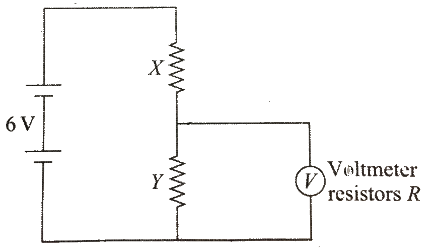
What is the reading of the voltmeter?
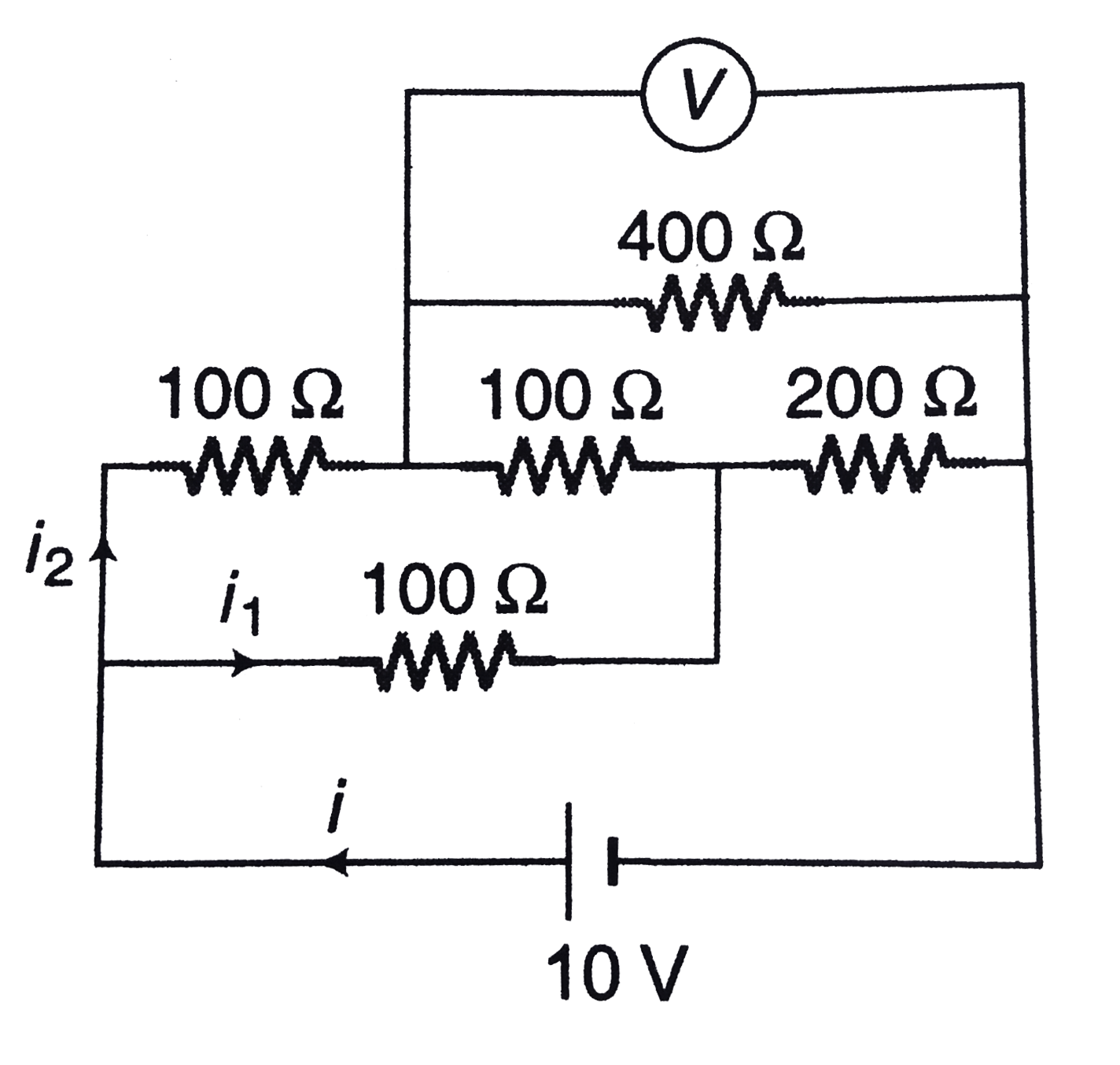
View SolutionAn electrical circuit is shown in figure. Calculate the potential difference across the resistor of 400Ω as will be measured by the voltmeter Vof resistance 400Ω either by applying Kirchhoff's rules or otherwise.
View SolutionFour equal resistors, each of resistance 10Ω, are connected as shown in the circuit diagram. The equivalent resistance between A and B is
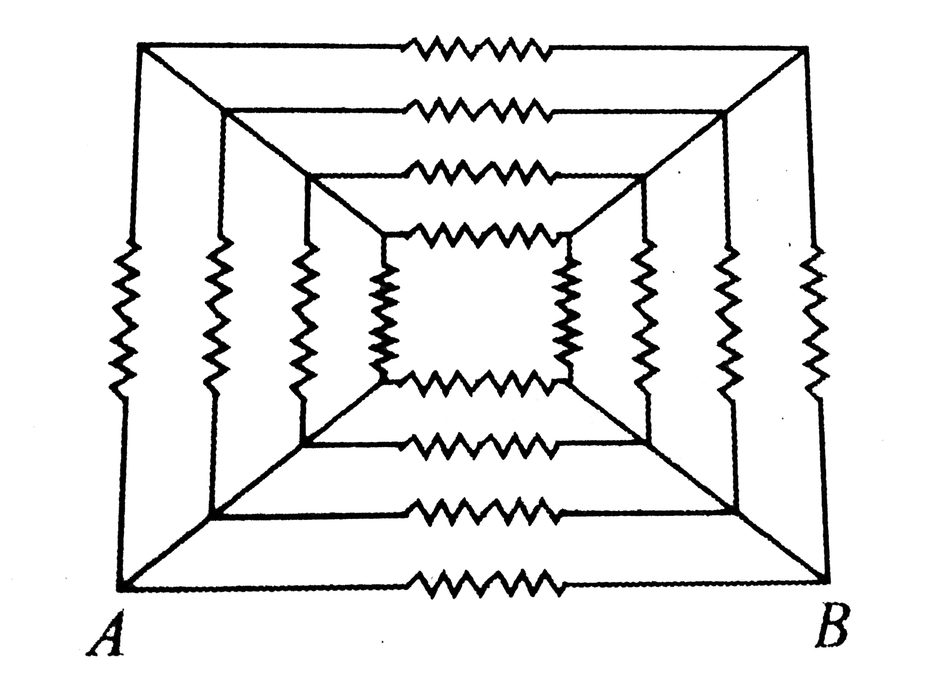
View SolutionSixteen resistor, each resistane 16Ω are connected in the circuit as shown in fig. the net resistance between A and B is
View Solution