shown a network of four resistance and three batteries
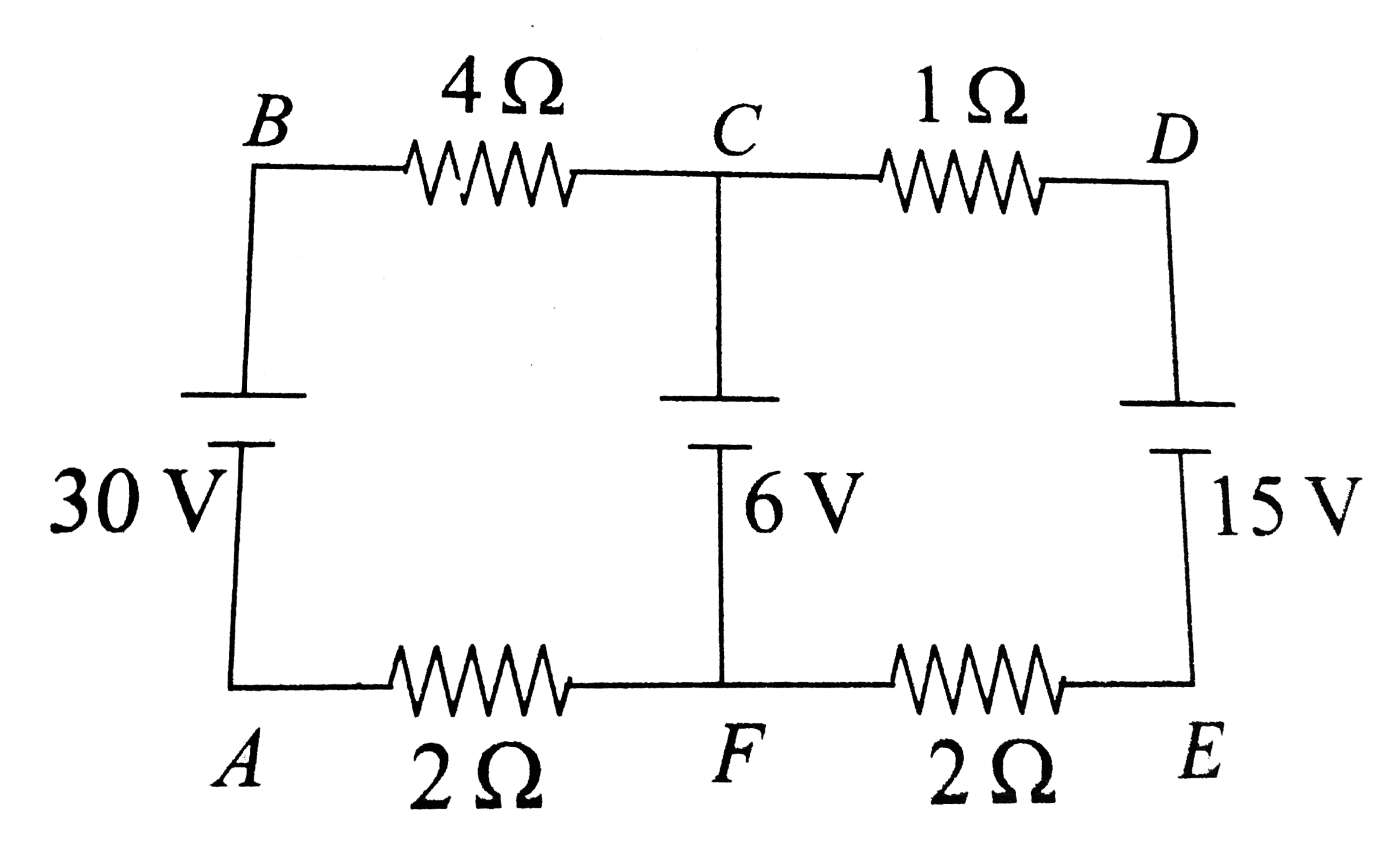
Choose the correct alternative.
The potential difference is VC−VF=6V.
No current flows in the branch CF.
Current flows in the branch from F to C.
Both (a) and (c )
The correct Answer is:A
Left loop :
VF+6+4I1−30+2I1=VF
I4=4A
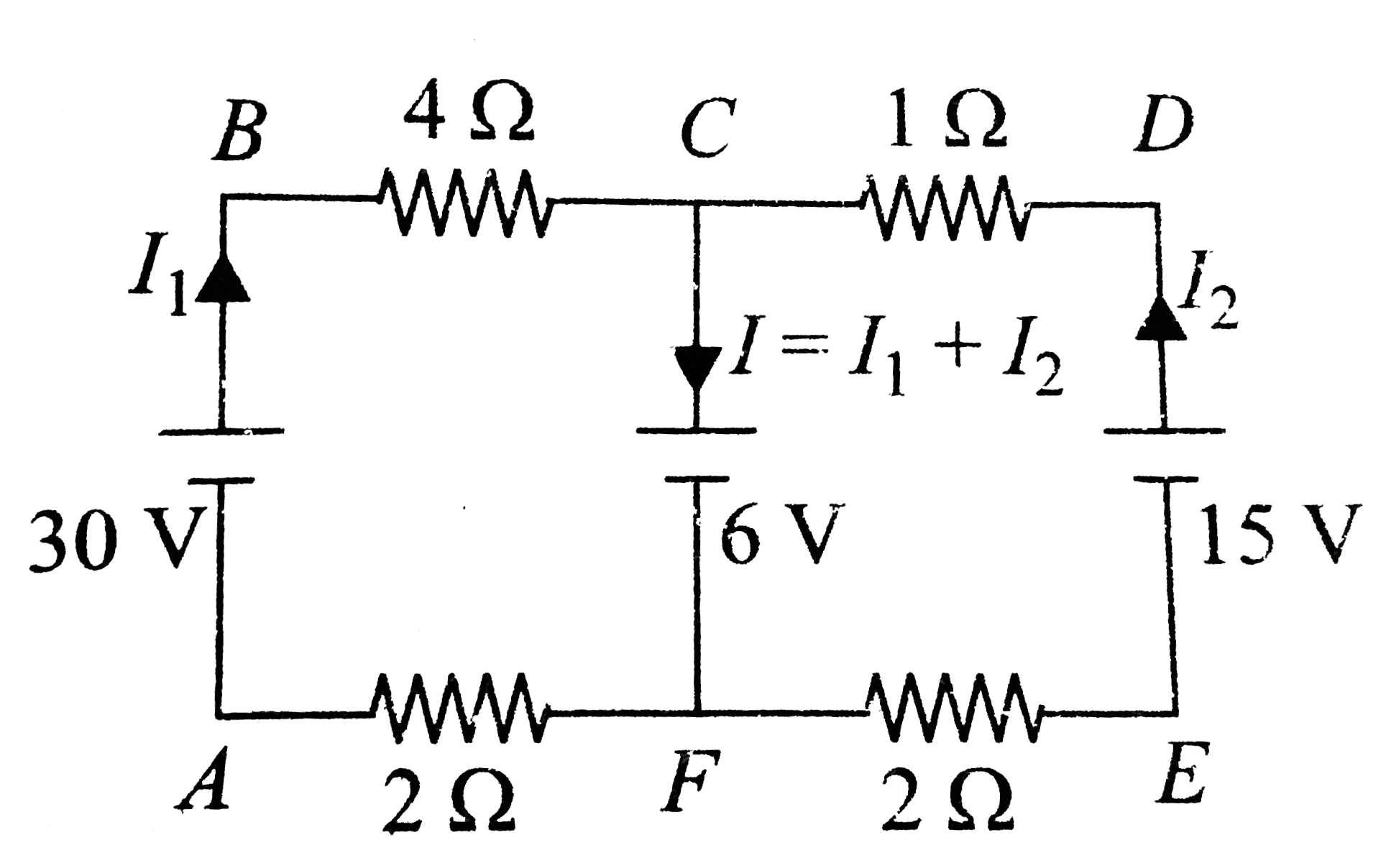
Right loop :
VF+6+1I2−15+2I2=VF30V
or I2=3A
Net current through 6V battery is
I=I1+I2=4+3=7A
The 6 V battery is getting charged. Both 15V and 30V batteries
produce current in 6V battery.
Topper's Solved these Questions
- ELECTRIC CURRENT AND CIRCUITBOOK - CENGAGE PHYSICS ENGLISHCHAPTER - ELECTRIC CURRENT AND CIRCUITEXERCISE - Interger
8 Videos
- ELECTRIC CURRENT AND CIRCUITBOOK - CENGAGE PHYSICS ENGLISHCHAPTER - ELECTRIC CURRENT AND CIRCUITEXERCISE - Multiple Correct
16 Videos
- ELECTRIC CURRENT & CIRCUITSBOOK - CENGAGE PHYSICS ENGLISHCHAPTER - ELECTRIC CURRENT & CIRCUITSEXERCISE - Kirchhoff s law and simple circuits
15 Videos
- ELECTRIC FLUX AND GAUSS LAWBOOK - CENGAGE PHYSICS ENGLISHCHAPTER - ELECTRIC FLUX AND GAUSS LAWEXERCISE - MCQ s
38 Videos
Similar Questions
Choose the correct alternatives
View Solutionshown a network of four resistance and three batteries
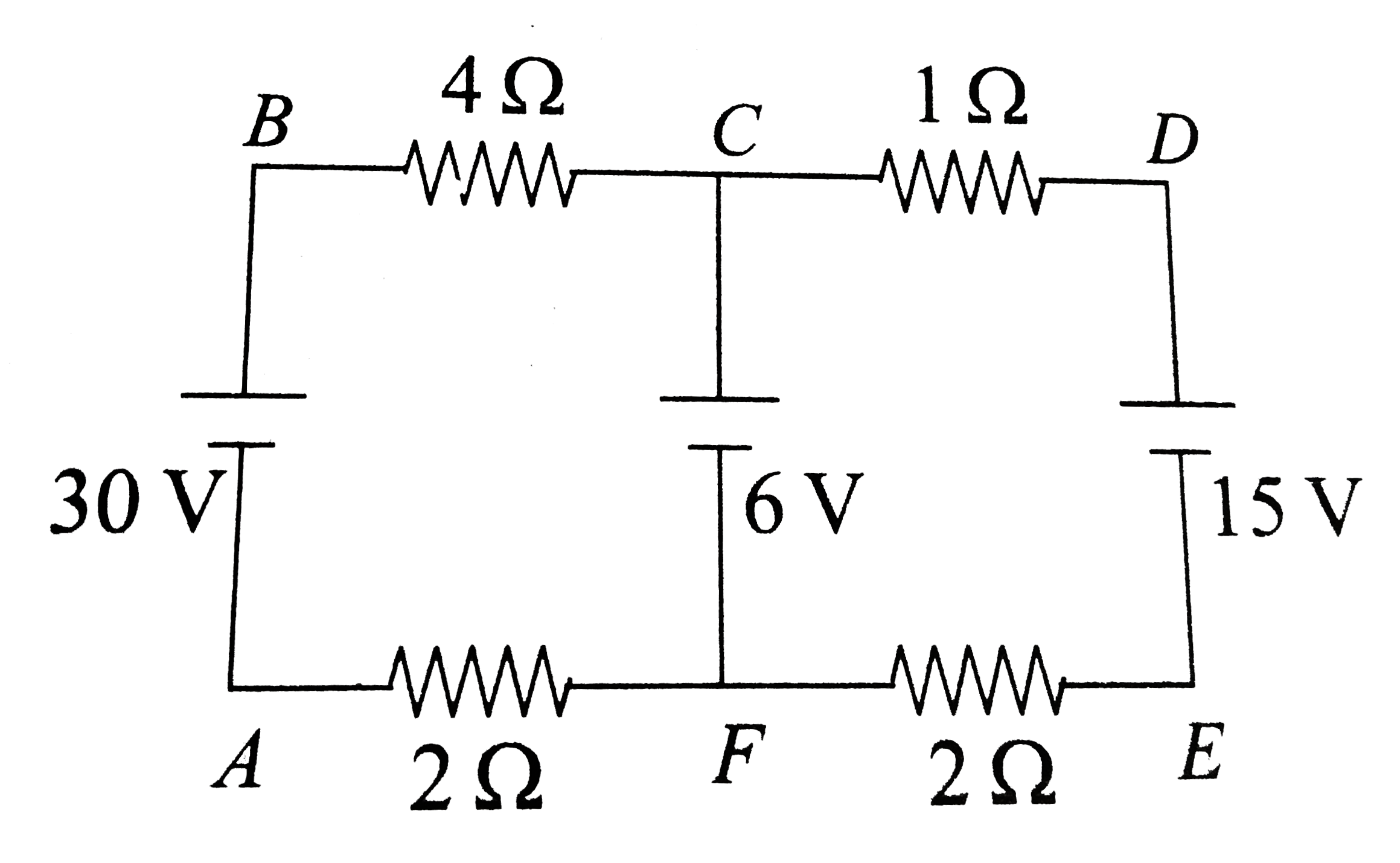
Mark the incorrect statement.
View Solutionshown a network of four resistance and three batteries
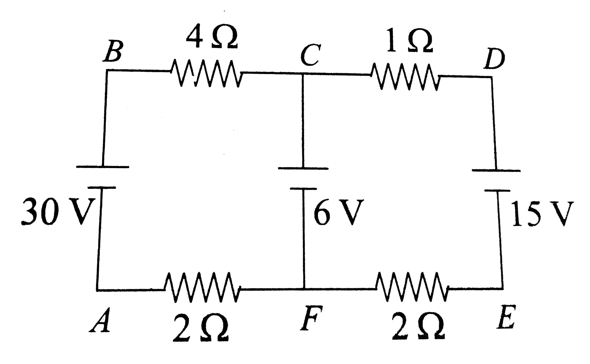
Which of the batteries is getting charged.
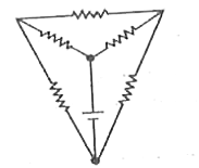
View SolutionIf all resistors in the shown network are of equal resistance, and the battery is of emf equal to 10 V and internal resistance equal to 1Ω, what should be resistance of each resistor so that the battery delivers maximum power
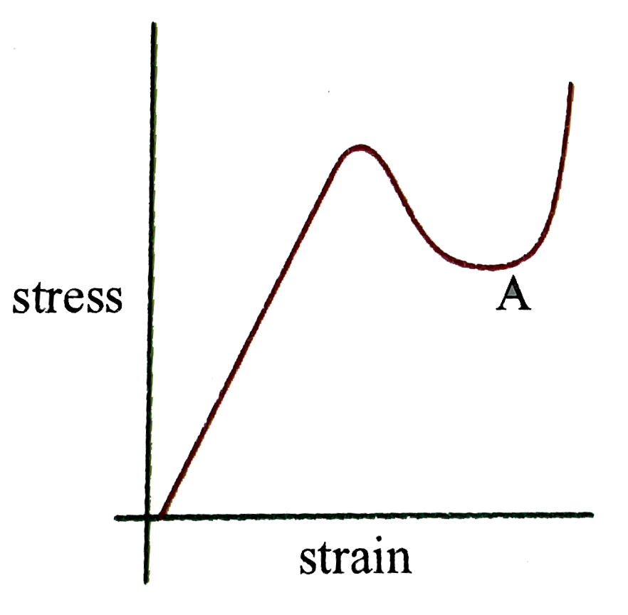
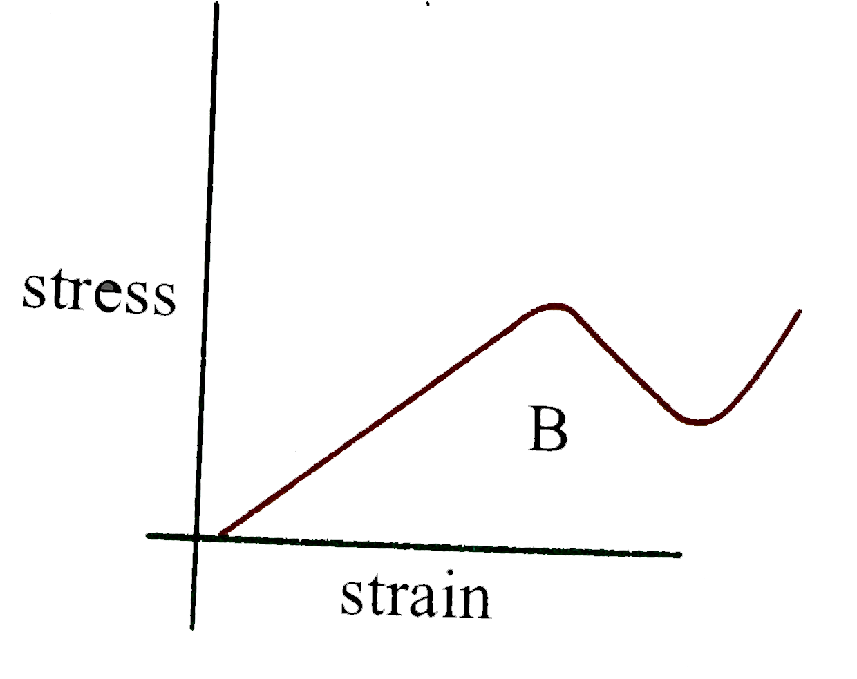
View SolutionThe stress- strain graphs for materials A and B are as shown. Choose the correct alternative
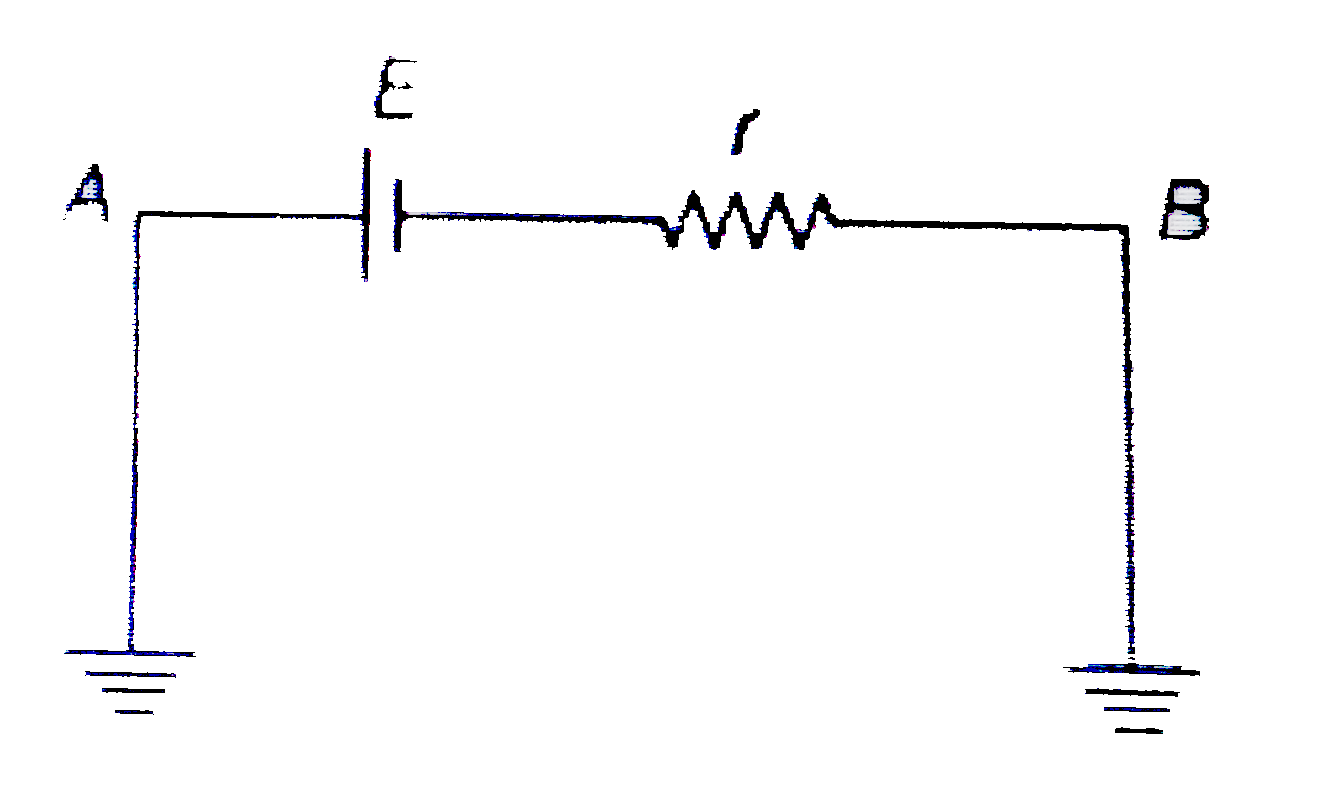
View SolutionBoth terminals of a battery of emf E and internal resistance r are grounded as shown. Select the correct alternative(s).
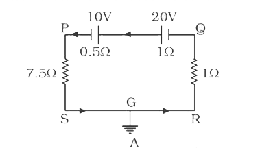
View SolutionIn the circuit shown, the internal resistances of the batteries are indicated next to them. Choose the correct option(s):
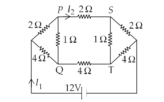
View SolutionFor the resistance network shown in the figure, choose the correct options (s)
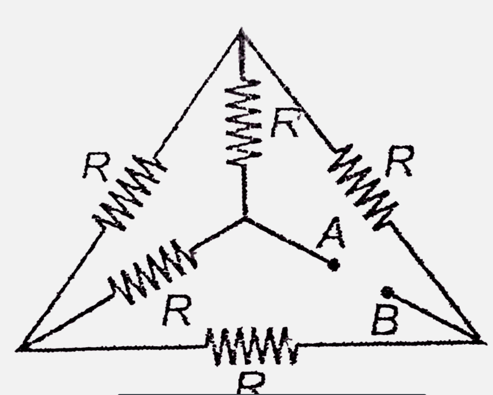
View SolutionIn the network shown , find the resistance across AB.
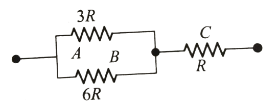
View SolutionFigure 7.37 shows a network of three resistances. When some potential difference is applied across the network , thermal powers dissipated by A,BandC are in the ratio
View Solution
