Draw a neatly labelled circuit diagram of a full wave rectifier using two junction diodes.
To draw a neatly labeled circuit diagram of a full wave rectifier using two junction diodes, follow these steps:
1. Draw the AC Source:
- Begin by drawing a sine wave symbol to represent the AC input source. Label it as "AC Source".
2. Add the Transformer:
- Next, draw a transformer symbol next to the AC source. This transformer will step down or step up the voltage as needed. Label the primary side as "Primary Coil" and the secondary side as "Secondary Coil".
3. Draw the Diodes:
- From the secondary coil, draw two diodes in parallel but facing opposite directions.
- Label the first diode as "D1" and the second diode as "D2".
- Ensure that the anode of D1 is connected to the positive terminal of the secondary coil and the cathode is connected to the output. For D2, the anode should connect to the output and the cathode to the negative terminal of the secondary coil.
4. Connect the Load Resistor:
- Draw a load resistor (R) connected to the output of the diodes. This represents the load where the rectified current will flow.
- Label this resistor as "Load Resistance".
5. Label the Points:
- Label the points in the circuit for clarity:
- A: AC Source
- B: Primary Coil
- C: Secondary Coil
- D: D1 (Diode 1)
- E: D2 (Diode 2)
- F: Load Resistance
- G: Output (DC)
6. Final Touches:
- Ensure all lines are straight and the diagram is neat. Use a ruler for straight lines and a pencil for clean drawing.
Complete Circuit Diagram:
- The final diagram should show the AC source connected to the primary coil of the transformer, with the secondary coil leading to the two diodes (D1 and D2) and then to the load resistor, with the output taken from the junction of the diodes and the load resistor.
- Begin by drawing a sine wave symbol to represent the AC input source. Label it as "AC Source".
- Next, draw a transformer symbol next to the AC source. This transformer will step down or step up the voltage as needed. Label the primary side as "Primary Coil" and the secondary side as "Secondary Coil".
- From the secondary coil, draw two diodes in parallel but facing opposite directions.
- Label the first diode as "D1" and the second diode as "D2".
- Ensure that the anode of D1 is connected to the positive terminal of the secondary coil and the cathode is connected to the output. For D2, the anode should connect to the output and the cathode to the negative terminal of the secondary coil.
- Draw a load resistor (R) connected to the output of the diodes. This represents the load where the rectified current will flow.
- Label this resistor as "Load Resistance".
- Label the points in the circuit for clarity:
- A: AC Source
- B: Primary Coil
- C: Secondary Coil
- D: D1 (Diode 1)
- E: D2 (Diode 2)
- F: Load Resistance
- G: Output (DC)
- Ensure all lines are straight and the diagram is neat. Use a ruler for straight lines and a pencil for clean drawing.
- The final diagram should show the AC source connected to the primary coil of the transformer, with the secondary coil leading to the two diodes (D1 and D2) and then to the load resistor, with the output taken from the junction of the diodes and the load resistor.
Similar Questions
Draw the circuit diagram of a half - wave rectifier using a p-n junction diode.
View Solution(a) Draw the circuit diagram of a full wave rectifier using p-n junction diole. Explain its working and show the output, input waveforms.
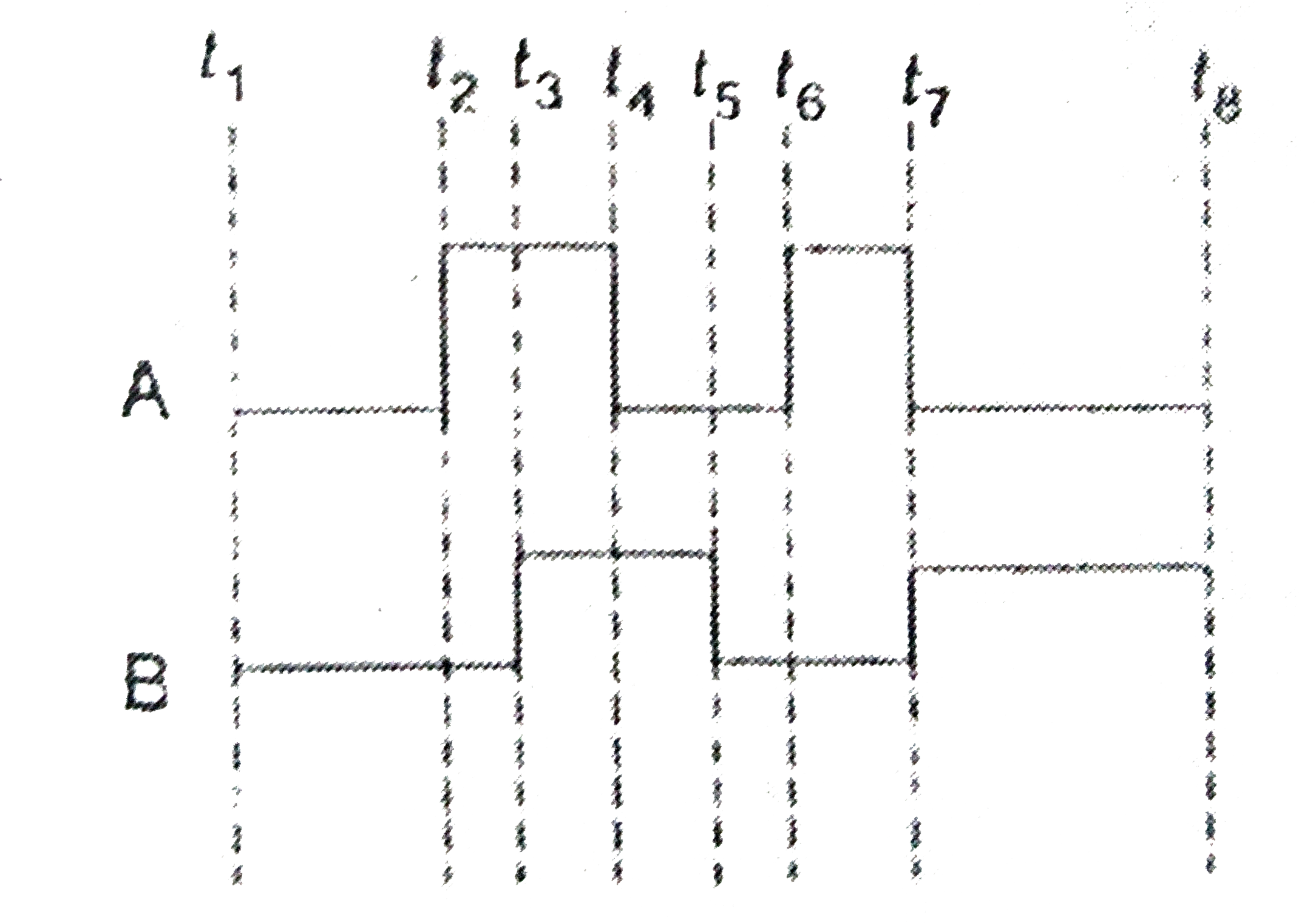
(b) Show the output waveforms (Y) for the following inputs A and B of (i) OR gate (ii) NAND gate :
 View Solution
Draw a neat and labelled diagram of a tooth.
View SolutionDraw a neat and labelled diagram of a neuron.
View SolutionDraw a neat labelled diagram of an animal cell.
View SolutionDraw a neat labelled diagram of a biogas plant.
View SolutionDraw a labelled circuit diagram of a half wave rectifier and give its output waveform.
View SolutionDraw a neat and labelled diagram of a plant cell.
View SolutionDraw a well labelled diagram of a DNA helix.
View SolutionDraw a neat labelled diagram of a laboratory thermometer
View Solution
