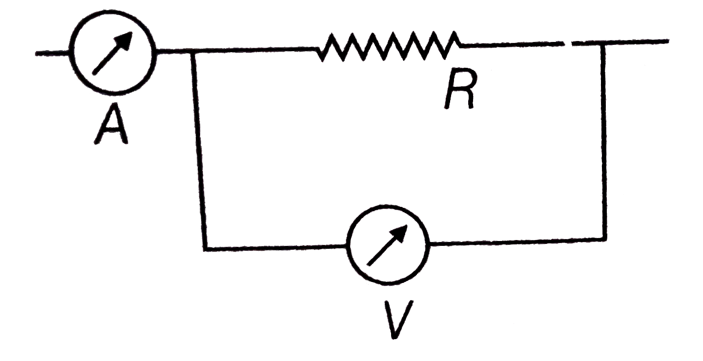
In the adjoining circuit diagram, the readings of ammeter and voltmeter are 2 A and 120 V, respectively. If the value of R is 75Ω, then the voltmeter resistance will be
100Ω
150Ω
300Ω
75Ω
The correct Answer is:C
∴VAB=(I−Ig)R=Ig.G
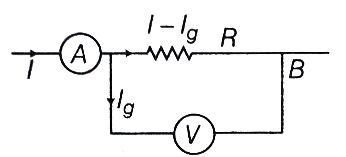
Where, G=voltmeter(resistance).
Given, VAB=120V,I=2A,R=75Ω
⇒120=(2−Ig)75⇒Ig=0.4A
Now, VAB=IgG⇒G=1200.4=300Ω
Topper's Solved these Questions
- SOLVED PAPERS 2018BOOK - DC PANDEY ENGLISHCHAPTER - SOLVED PAPERS 2018EXERCISE - Assertion and Reasons
10 Videos
- SOLVED PAPERS 2018BOOK - DC PANDEY ENGLISHCHAPTER - SOLVED PAPERS 2018EXERCISE - JIPMER
22 Videos
- SOLVED PAPERS 2018BOOK - DC PANDEY ENGLISHCHAPTER - SOLVED PAPERS 2018EXERCISE - JIPMER
22 Videos
- SOLVED PAPER 2017BOOK - DC PANDEY ENGLISHCHAPTER - SOLVED PAPER 2017EXERCISE - Solved papers 2017(JIPMER)
32 Videos
- WAVE OPTICSBOOK - DC PANDEY ENGLISHCHAPTER - WAVE OPTICSEXERCISE - For JEE Advanced E. Integer Type Questions
13 Videos
Similar Questions
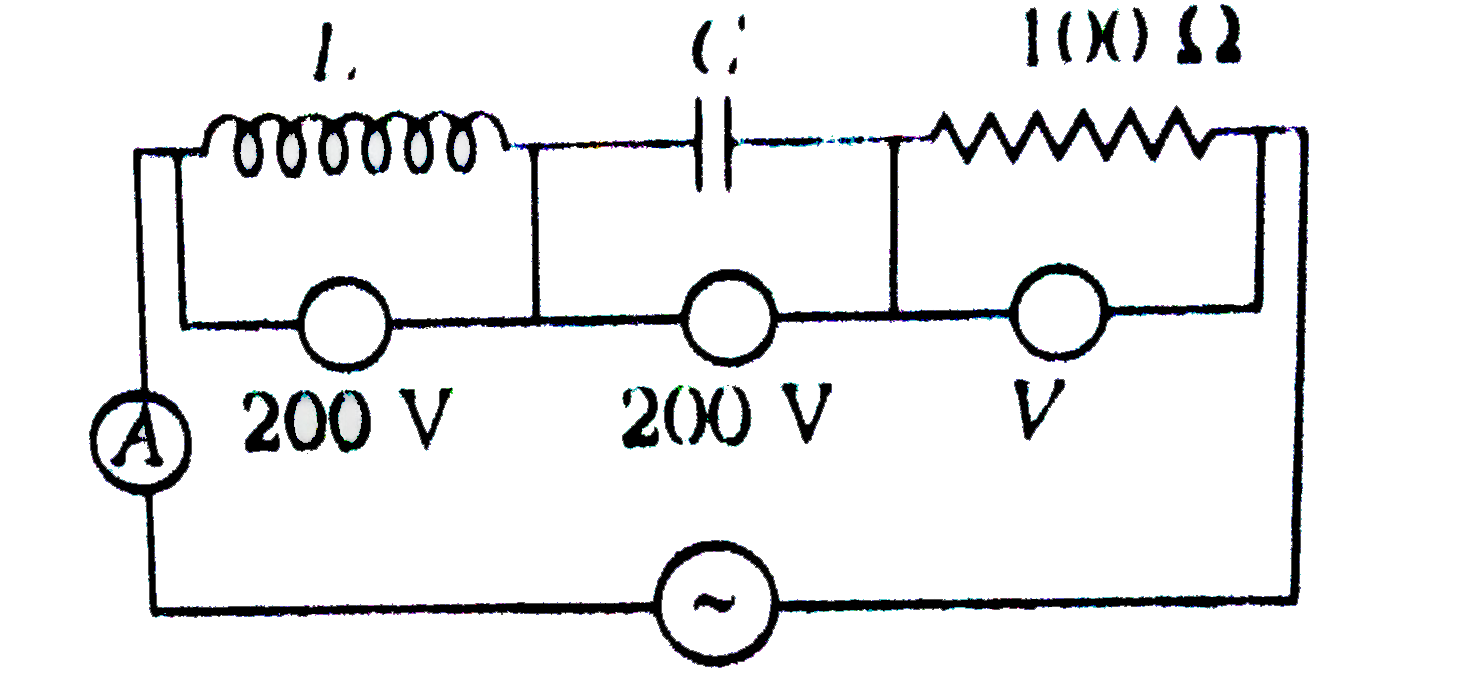
In the circuit shown here, the readings of the ammeter and voltmeter are
View SolutionIn the circuit shown the reading of ammeter and voltmeter are 4A and 20V respectively. The meters are non ideal, then R ia
View SolutionThe reading of ammeter and voltmeter in the given circuit is
_PHY_E06_306_Q01.png)
View SolutionThe reading of ammeter and voltmeter in the following circuit are respectively
View SolutionIn the circuit shown alongside, the ammeter and the voltmeter redings are 3A and 6V, respectively. Then, the value of the resistance R is

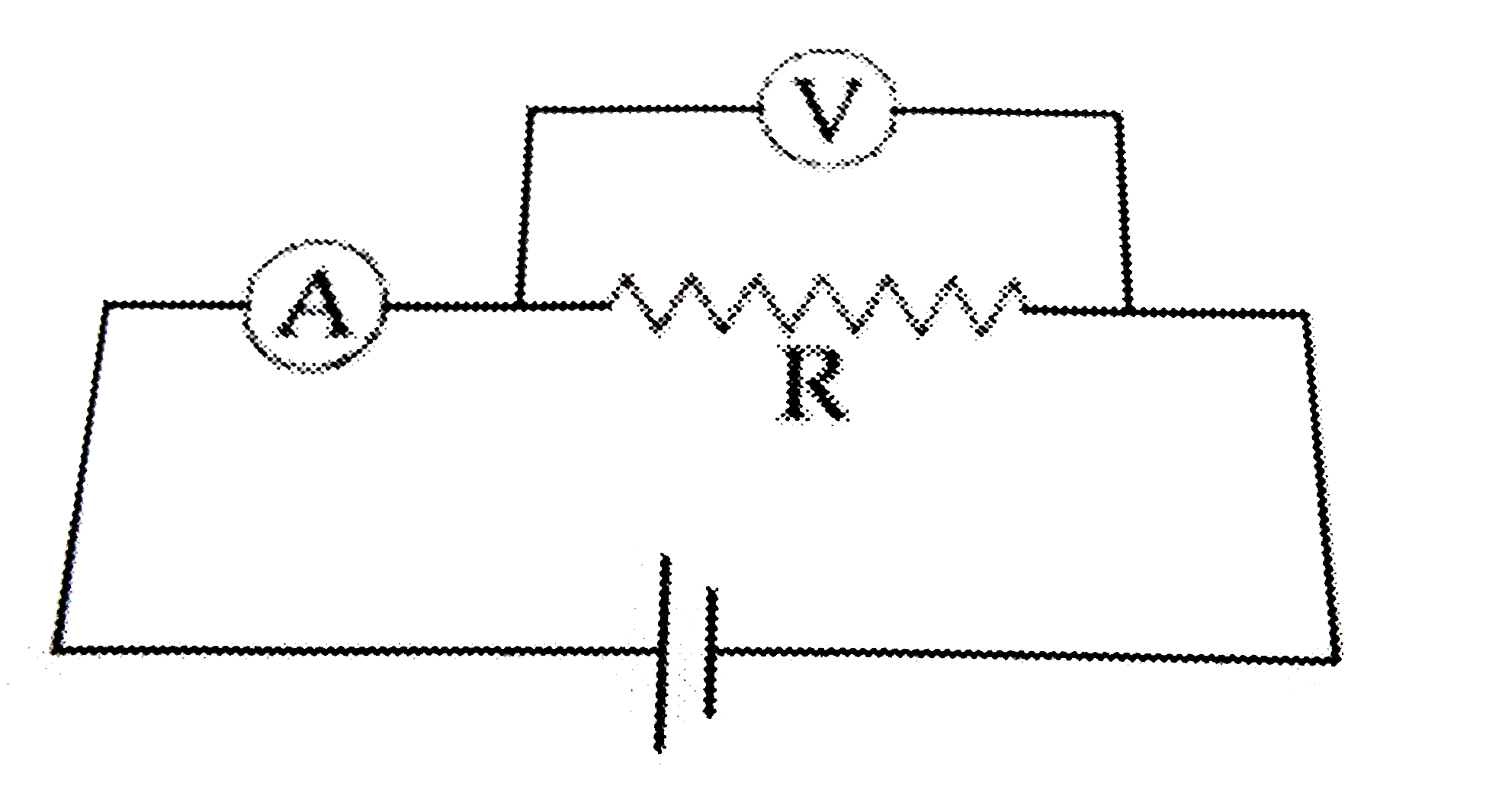
View SolutionThe actual value of resistance R, shown in the figure is 30Ω. This is measured in an experiment as shown using the standard formula R=VI, where V and I are the readings of the voltmeter and ammeter, respectively. If the measured value of R is 5% less, then the internal resistance of the voltmeter is
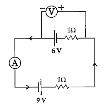
View SolutionIn the following circuit, determine the reading of ideal voltmeter (V) and ideal ammeter (A).
View SolutionIn the circuit shown in figure, what will be the readings of voltmeter and ammeter?
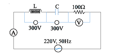
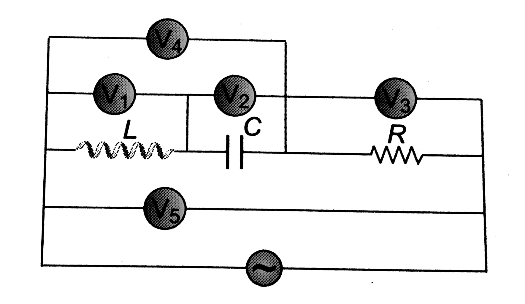
View SolutionIn the adjoining AC circuit the voltmeter whose reading will be zero at resonance is
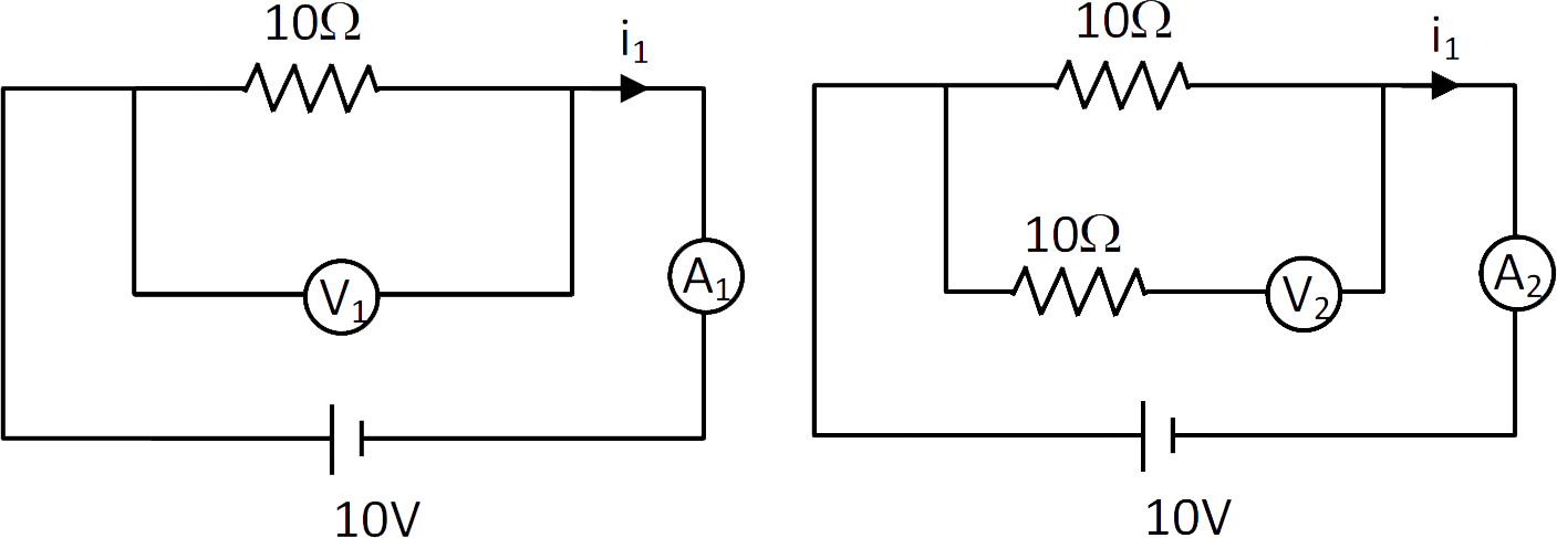
View SolutionIn the circuits shown below, the readings of the voltmeters and the ammeters will be:
View Solution
