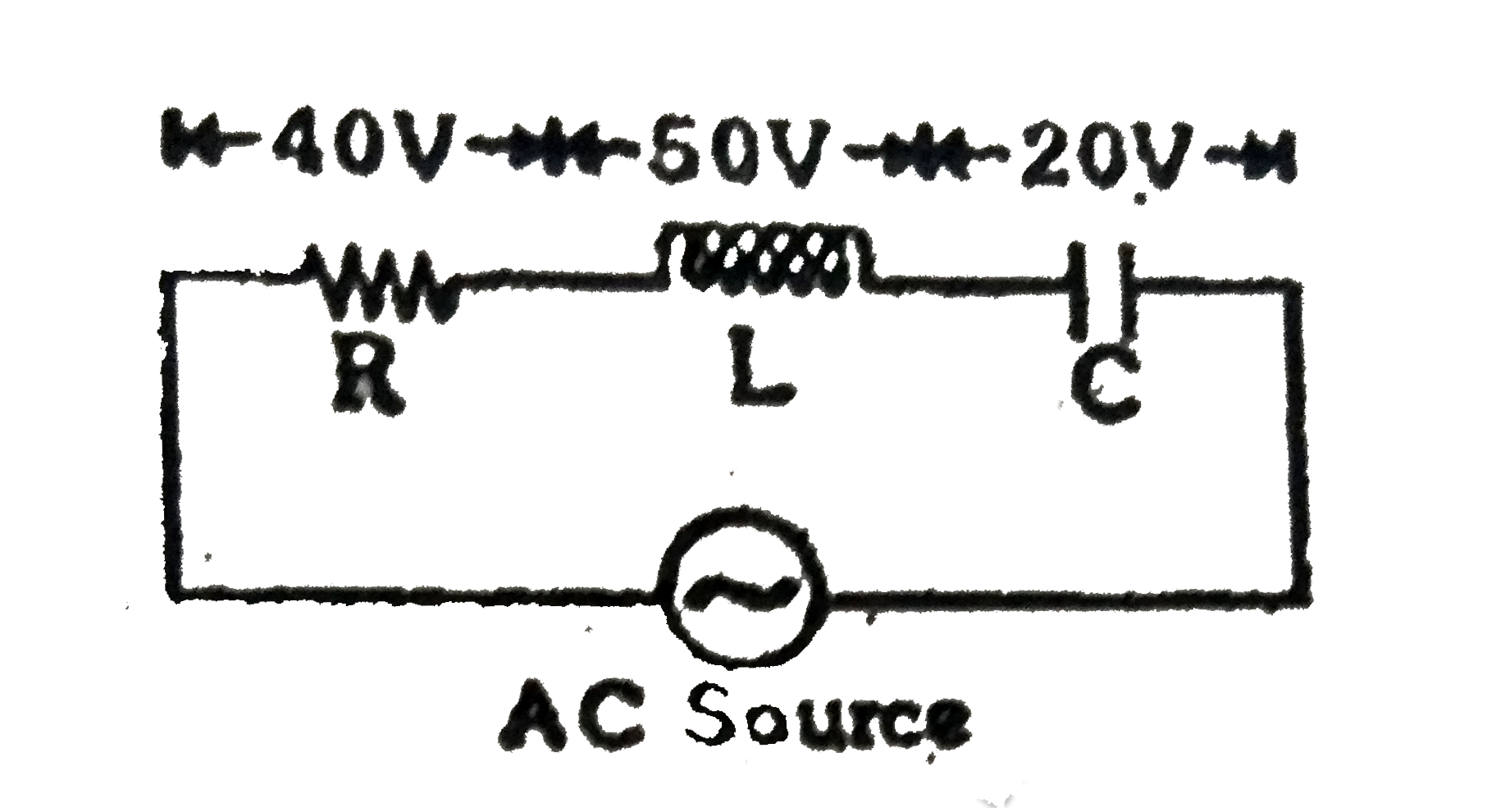
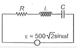
In a series L-C-R circuit the voltage across resistance , capacitance and inductance is 10 V each. If the capacitance is short circuited, the voltage across the inductance will be
10/√2 V
10 V
20√2 V
20 V
The correct Answer is:A
To solve the problem, we will analyze the series L-C-R circuit step by step.
Step 1: Understand the Given Information
We know that in the series L-C-R circuit:
- Voltage across the resistor (V_R) = 10 V
- Voltage across the capacitor (V_C) = 10 V
- Voltage across the inductor (V_L) = 10 V
Step 2: Write the Expression for the Source Voltage (V_s)
In a series L-C-R circuit, the source voltage (V_s) can be calculated using the formula:
Vs=√V2R+(VC−VL)2
Step 3: Substitute the Known Values
Since V_C and V_L are both equal to 10 V, we can substitute:
Vs=√V2R+(10−10)2
Vs=√V2R
Vs=VR
Thus, we have:
Vs=10V
Step 4: Analyze the Effect of Short-Circuiting the Capacitor
When the capacitor is short-circuited, the voltage across the capacitor (V_C) becomes 0 V. Therefore, we can update our expression for the source voltage:
Vs=√V2R+V2L
Since V_C = 0, we can ignore it in the equation.
Step 5: Substitute the Values Again
Now, we can write:
Vs=√V2R+V2L
Substituting V_R = 10 V:
10=√102+V2L
10=√100+V2L
Step 6: Square Both Sides to Eliminate the Square Root
Squaring both sides gives us:
100=100+V2L
Subtracting 100 from both sides:
0=V2L
This indicates that we need to re-evaluate our approach since we have neglected the phase difference.
Step 7: Correctly Calculate V_L
From the original formula for V_s:
Vs=√V2R+V2L
Since V_C = 0, we can say:
VL=Vs√2
Substituting V_s = 10 V:
VL=10√2
VL=10⋅√22
VL=5√2V
Conclusion
The voltage across the inductance when the capacitance is short-circuited is 10√2V.
---
We know that in the series L-C-R circuit:
- Voltage across the resistor (V_R) = 10 V
- Voltage across the capacitor (V_C) = 10 V
- Voltage across the inductor (V_L) = 10 V
In a series L-C-R circuit, the source voltage (V_s) can be calculated using the formula:
Vs=√V2R+(VC−VL)2
Since V_C and V_L are both equal to 10 V, we can substitute:
Vs=√V2R+(10−10)2
Vs=√V2R
Vs=VR
Thus, we have:
Vs=10V
When the capacitor is short-circuited, the voltage across the capacitor (V_C) becomes 0 V. Therefore, we can update our expression for the source voltage:
Vs=√V2R+V2L
Since V_C = 0, we can ignore it in the equation.
Now, we can write:
Vs=√V2R+V2L
Substituting V_R = 10 V:
10=√102+V2L
10=√100+V2L
Squaring both sides gives us:
100=100+V2L
Subtracting 100 from both sides:
0=V2L
This indicates that we need to re-evaluate our approach since we have neglected the phase difference.
From the original formula for V_s:
Vs=√V2R+V2L
Since V_C = 0, we can say:
VL=Vs√2
Substituting V_s = 10 V:
VL=10√2
VL=10⋅√22
VL=5√2V
The voltage across the inductance when the capacitance is short-circuited is 10√2V.
Similar Questions
In a series LCR the voltage across resistance, capacitance and inductance is 10V each. If the capacitance is shor t circulated, the voltage across the inducatance will be
View SolutionIn series LCR circuit voltage drop across resistance is 8V, across inductor is 6V and across capacitor is 12V. Then
View Solution
Knowledge Check
In a series LCR circuit, the voltage across the resistance, capacitance and inductance is 10 V each. If the capacitance is short circuited, the voltage across the inductance will be
A10VB10√2VC10√2VD20V
In series L−C−R circuit, voltge drop across resistance is 8V, across inductor is 6V and across capacitor is 12V. Then,
View SolutionIn a series resonant circuit, the ac, voltage across resistance R, inductance L and capacitance are 5V, 10V and 10V, respectively. The ac. voltage applied to the circuit will be
View SolutionIn a series LCR circuit the rms voltage across the inductance , capacitance and resistance are respectively 4 V, 8 V and 5 V . The RMS voltage of the AC source in the circuit is
View SolutionIn series LCR circuit, the voltages across R, L and C are shown in the figure. The voltage of applied source

View SolutionIn a series RLC circuit the r.m.s. voltage across the resistor and the inductor are respectively 400 V and 700 V. If the equation for the applied Voltage is ε=500√2sinωt. then the peak voltage across the capacitor is

View SolutionThe potential differences across the resistance, capacitance and inductance are 80V,40V and 100V respectively in an L−C−R circuit. The power factor of this circuit is
View SolutionIn an L-C-R series circuit, the potential difference between the terminals of the inductance is 60 V, between the terminals of the capacitor is 30 V and that across the resistance is 40 V. Then, the supply voltage will be equal to
View Solution

