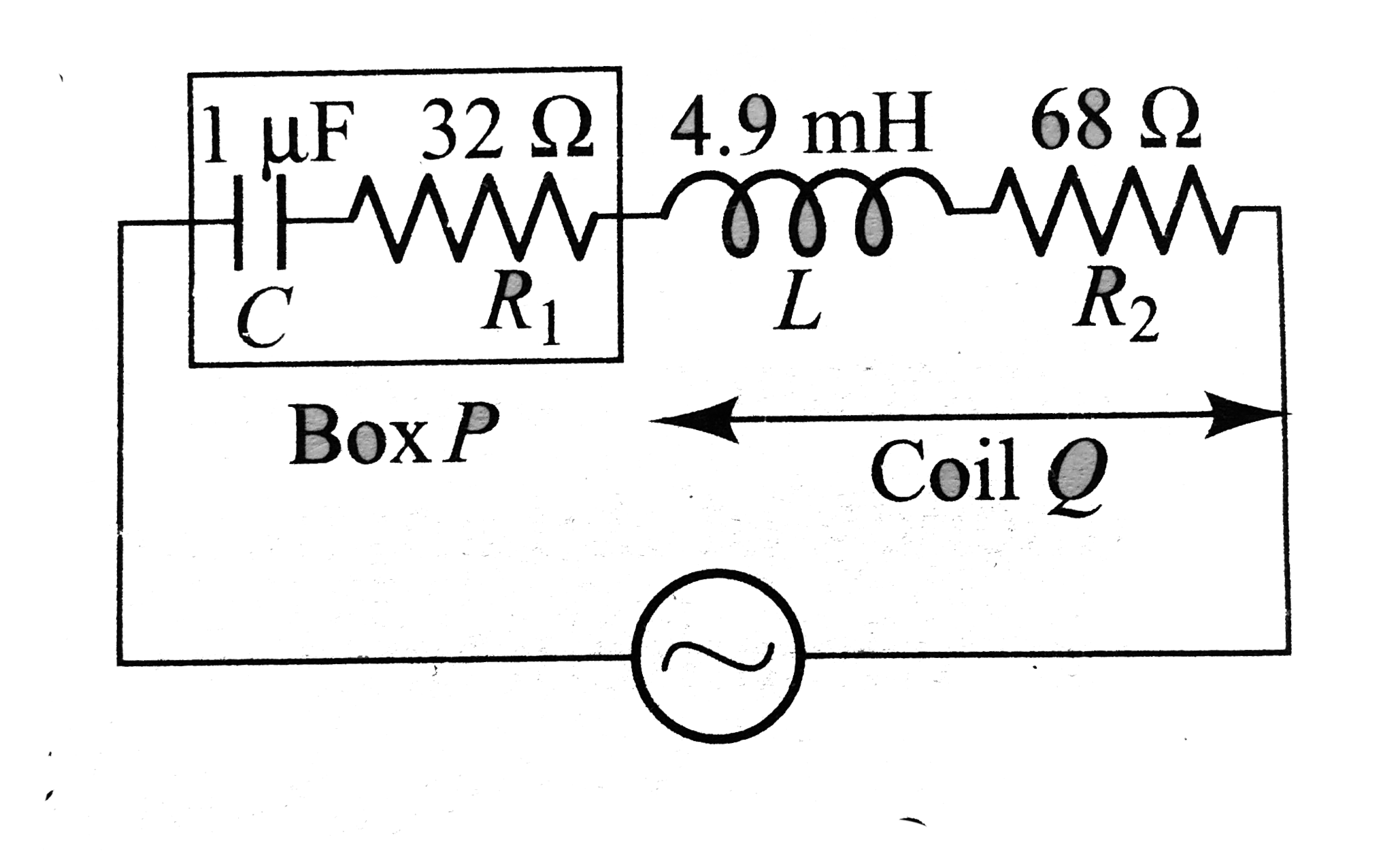
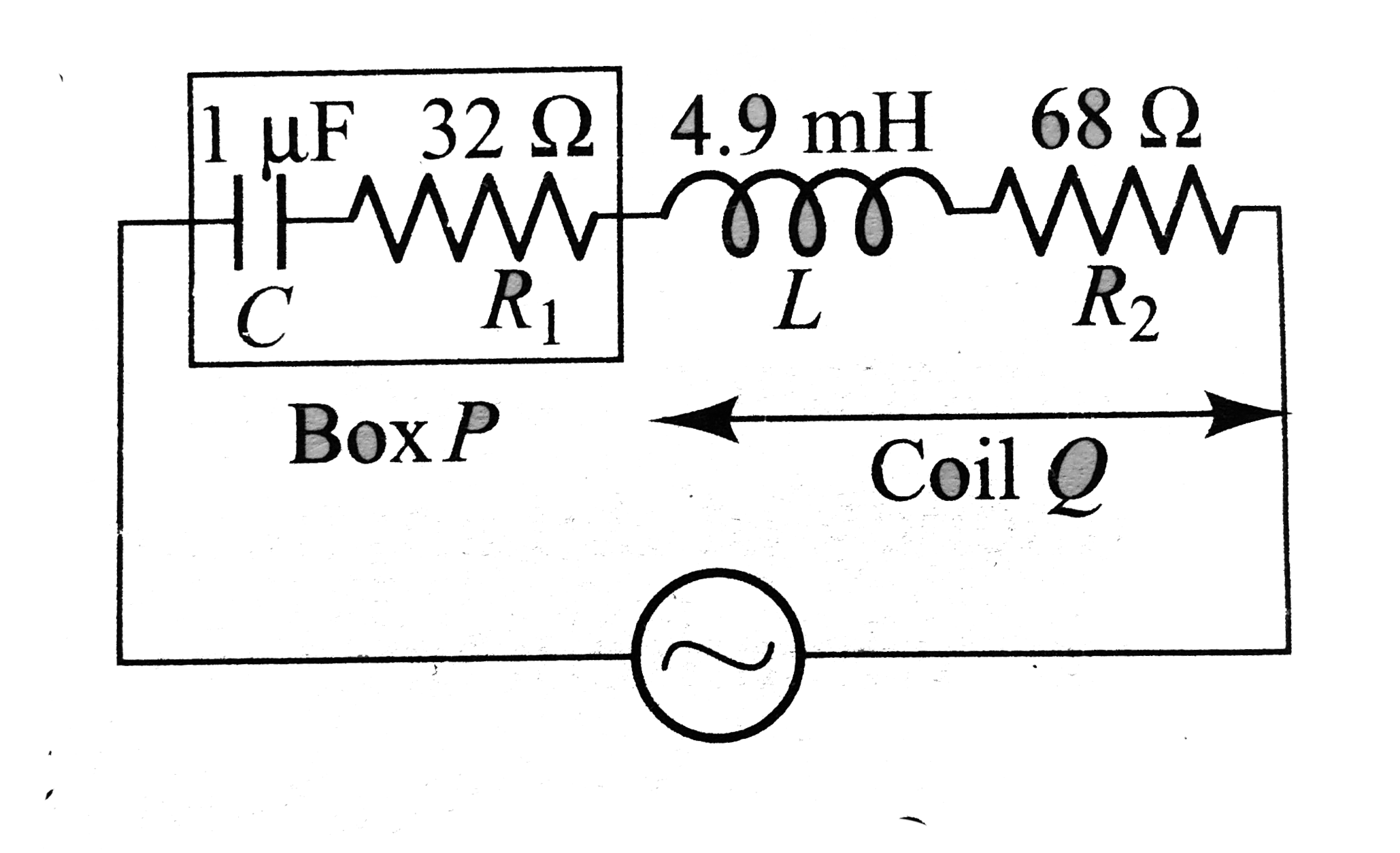
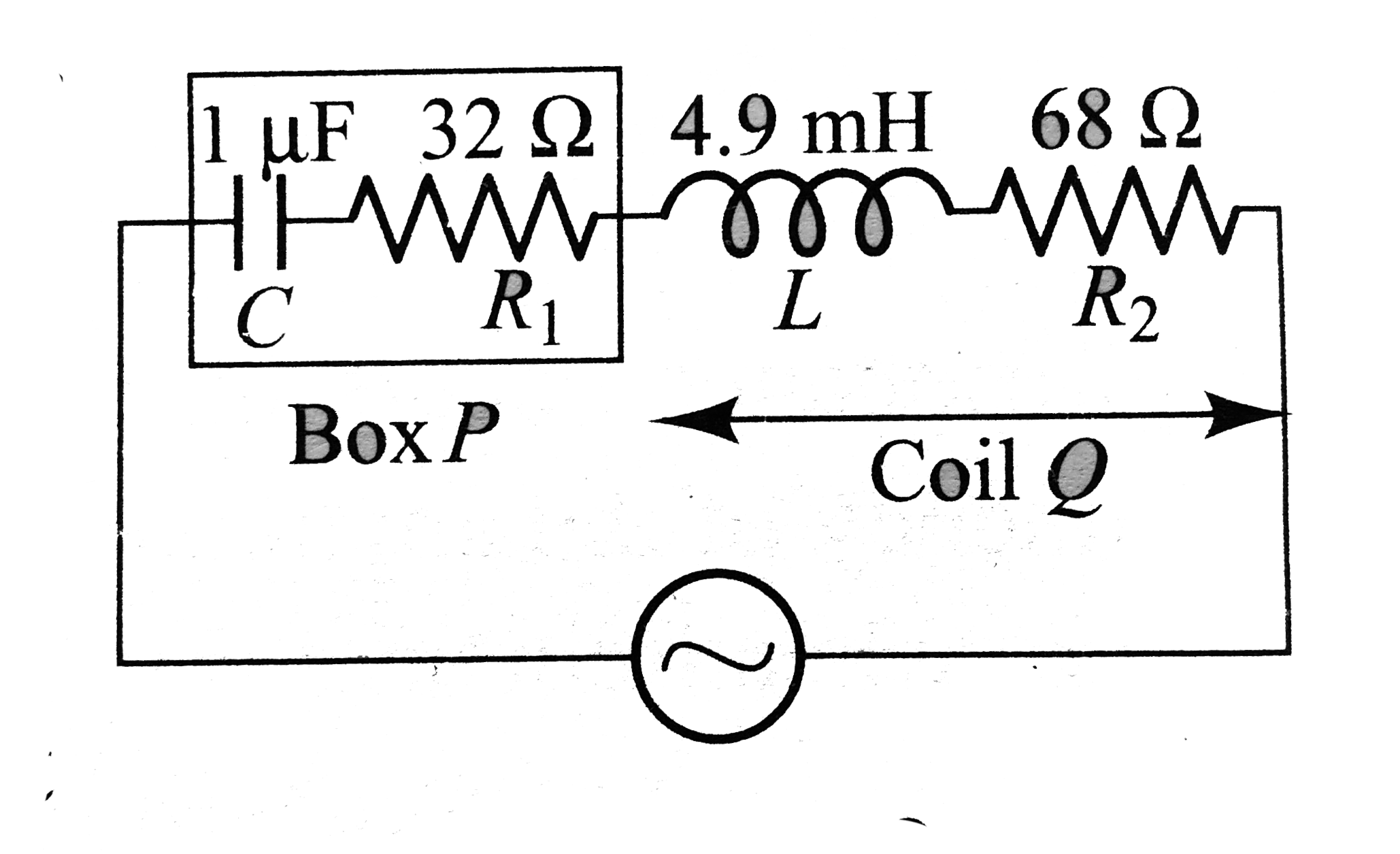
It is known to all of you that the impedance of a circuit is dependent on the frequency of source. In order to study the effect of frequency on the impedance, a student in a lab took 2 impedance boxes P and Q and connected them in series with an AC source of variable frequency. The emf of the source is constant at 10V Box P contains a capacitance of 1μF in series with a resistance of 32Ω. And the box Q has a coil of self-inductance 4.9mH and a resistance of 68Ωin series. He adjusted the frequency so that the maximum current flows in P and Q. Based on his experimental set up and the reading by him at various moment, answer the following questions.
Power factor of the circuit at maximum current is
12
1
0
1√2
The correct Answer is:B
To find the power factor of the circuit at maximum current, we can follow these steps:
Step 1: Understand the Condition for Maximum Current
At maximum current, the circuit is at resonance. This means that the inductive reactance (XL) and capacitive reactance (XC) are equal.
Step 2: Identify the Components in the Circuit
- For Box P:
- Capacitance (C) = 1 µF = 1 × 10^-6 F
- Resistance (R1) = 32 Ω
- For Box Q:
- Inductance (L) = 4.9 mH = 4.9 × 10^-3 H
- Resistance (R2) = 68 Ω
Step 3: Calculate the Reactances
- The capacitive reactance (XC) can be calculated using the formula:
XC=12πfC
- The inductive reactance (XL) can be calculated using the formula:
XL=2πfL
Step 4: Set the Reactances Equal at Resonance
At resonance, we have:
XL=XC
This means:
2πfL=12πfC
Step 5: Calculate the Total Resistance
The total resistance (R_total) in the circuit is the sum of the resistances from both boxes:
Rtotal=R1+R2=32Ω+68Ω=100Ω
Step 6: Calculate the Total Impedance at Resonance
At resonance, the total impedance (Z) is equal to the total resistance:
Z=Rtotal=100Ω
Step 7: Calculate the Power Factor
The power factor (PF) is given by:
PF=cosϕ=RZ
Substituting the values:
PF=100Ω100Ω=1
Conclusion
The power factor of the circuit at maximum current is 1.
---
At maximum current, the circuit is at resonance. This means that the inductive reactance (XL) and capacitive reactance (XC) are equal.
- For Box P:
- Capacitance (C) = 1 µF = 1 × 10^-6 F
- Resistance (R1) = 32 Ω
- Inductance (L) = 4.9 mH = 4.9 × 10^-3 H
- Resistance (R2) = 68 Ω
- The capacitive reactance (XC) can be calculated using the formula:
XC=12πfC
- The inductive reactance (XL) can be calculated using the formula:
XL=2πfL
At resonance, we have:
XL=XC
This means:
2πfL=12πfC
The total resistance (R_total) in the circuit is the sum of the resistances from both boxes:
Rtotal=R1+R2=32Ω+68Ω=100Ω
At resonance, the total impedance (Z) is equal to the total resistance:
Z=Rtotal=100Ω
The power factor (PF) is given by:
PF=cosϕ=RZ
Substituting the values:
PF=100Ω100Ω=1
The power factor of the circuit at maximum current is 1.
Topper's Solved these Questions
- ALTERNATING CURRENTBOOK - DC PANDEY ENGLISHCHAPTER - ALTERNATING CURRENTEXERCISE - Level 2 Subjective
10 Videos
- ALTERNATING CURRENTBOOK - DC PANDEY ENGLISHCHAPTER - ALTERNATING CURRENTEXERCISE - JEE MAIN
62 Videos
- ALTERNATING CURRENTBOOK - DC PANDEY ENGLISHCHAPTER - ALTERNATING CURRENTEXERCISE - Level- 2More Than One Correct
8 Videos
- ATOMSBOOK - DC PANDEY ENGLISHCHAPTER - ATOMSEXERCISE - MEDICAL ENTRANCES GALLERY
42 Videos
Similar Questions
It is known to all of you that the impedance of a circuit is dependent on the frequency of source. In order to study the effect of frequency on the impedance, a student in a lab took 2 impedance boxes P and Q and connected them in series with an AC source of variable frequency. The emf of the source is constant at 10V Box P contains a capacitance of 1μF in series with a resistance of 32Ω. And the box Q has a coil of self-inductance 4.9mH and a resistance of 68Ωin series. He adjusted the frequency so that the maximum current flows in P and Q. Based on his experimental set up and the reading by him at various moment, answer the following questions.
Impedance of box P at the above frequency is
View SolutionIt is known to all of you that the impedance of a circuit is dependent on the frequency of source. In order to study the effect of frequency on the impedance, a student in a lab took 2 impedance boxes P and Q and connected them in series with an AC source of variable frequency. The emf of the source is constant at 10V Box P contains a capacitance of 1μF in series with a resistance of 32Ω. And the box Q has a coil of self-inductance 4.9mH and a resistance of 68Ωin series. He adjusted the frequency so that the maximum current flows in P and Q. Based on his experimental set up and the reading by him at various moment, answer the following questions.
The angular frequency foer which he detects maximum current in the circuit is
View Solution
Knowledge Check
A box P and a coil Q are connected in series with an ac source of variable frequency. The emf of the source is constant at 10 V. Box P xontains a capacitance of 32Ω. Coil Q has a self inductance of 4.9 mH and a resistance of 68Ω in series. The frequency is adjusted so that maximum current flows in P and Q.

The impendance of Q at this frequency isA9.76V,8.92VB6.29V,7.96VC7.70V,10.92VD7.70V,9.76V
A box P and a coil Q are connected in series with an ac source of variable frequency. The emf of the source is constant at 10 V. Box P contains a capacitance 1μf and a resistance of 32Ω. Coil Q has a self inductance of 4.9 mH and a resistance of 68Ω in series. The frequency is adjusted so that maximum current flows in P and Q.

The voltage across P is
View SolutionA box P and a coil Q are connected in series with an AC source of variable frequency.The EMF of source is constant at 10V.Box P contains a capacitance of 1μF in series with a resistance of 32Ω.Coil Q has a self inductance 4.9mH and a resistance of 68Ω.The frequency is adjusted so that the maximum current flows in P and Q.Find the impedance of P and Q at this frequency.Also find the voltage across P and Q respectively.
View SolutionA box P and a coil Q are connected in series with an ac source of variable frequency. The emf of the source is constant at 10 V. Box P contains a capacitance of 32Ω. Coil Q has a self inductance of 4.9 mH and a resistance of 68Ω in series. The frequency is adjusted so that maximum current flows in P and Q.

The impedance of P at this frequency is
View SolutionA bulb and a conender are connected in series with an A.C source. On increasing the frequency of the source its brightness will
View SolutionFor an LCR series circuit with an aac source of angular frequency ω.
View SolutionFor an LCR series circuit with an ac source of angular frequency ω.
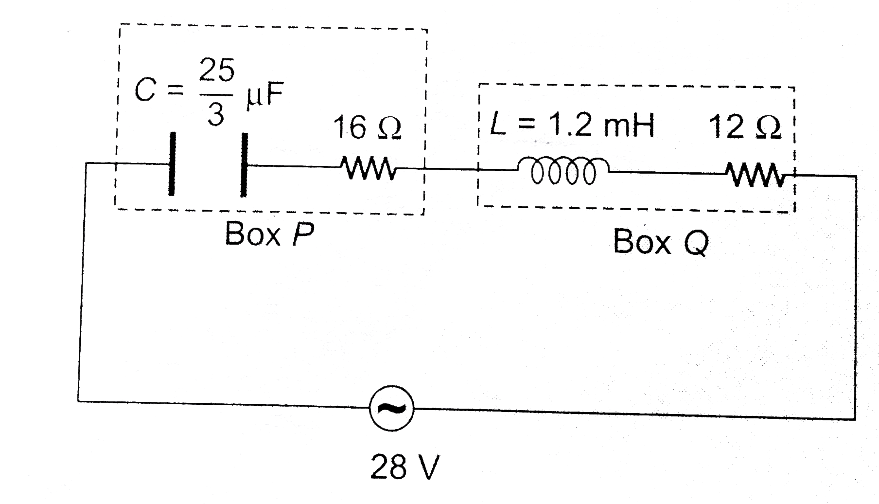
View SolutionA box P and a coil Q are connected in series with an ac source of variable freguency The emf of the source is constant at 28V The frequency is so adjusted that the maximum current flows in P and Q Find
(a) impedance of P and Q at this frequency
(b) voltage across P and Q
 .
.
View Solution
