In the circuit shown in figure
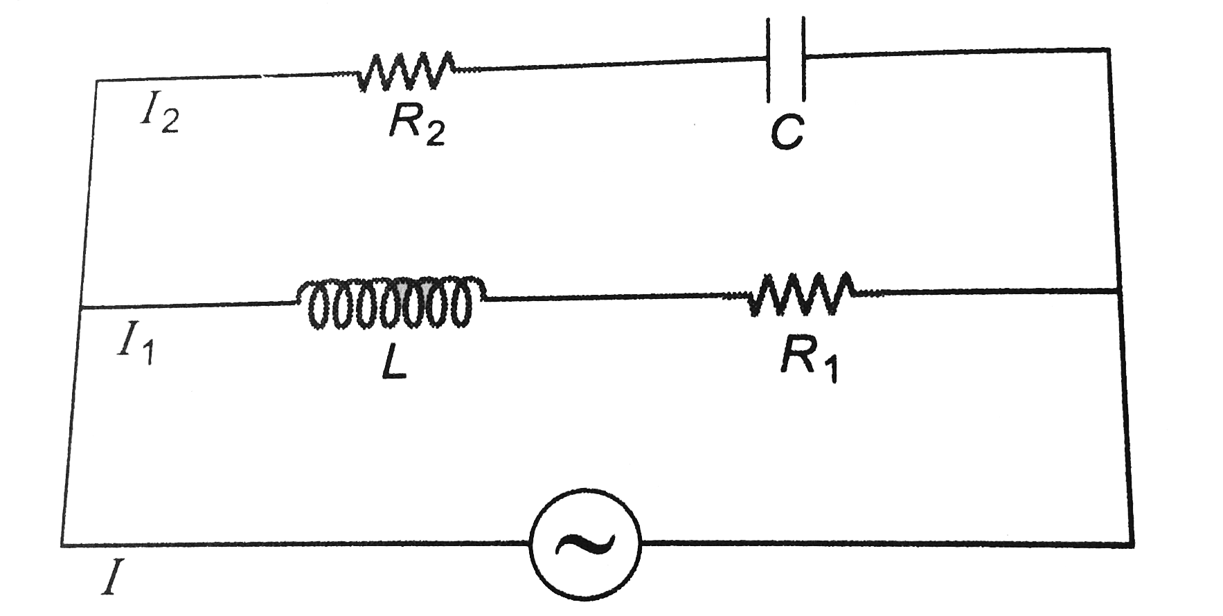
R1=30Ω,R2=40Ω,L=0.4H and C=13mF.
Find seven function of time I,I1,I2,VR1,VL,VR2 and VC. Also total power consumed in the circuit. In the given potential function V is in volts and omega rad/s V=200 sin(100t+30)
Circuit 1 (containing L and R1)
I1:XL=ωL=100×0.4=40Ω
R1=30Ω
∴Z1=√R21+X2L=√(30)2+(40)2
=50Ω ltbRgt Maximum value of current I1=V0Z1=20050=4A
Since there is only XL so voltage function will lead the current function by angle ϕ1, where
cosϕ1=R1Z1=3050=35
∴ϕ1=53∘
∴I1=4sin(100t+30∘−53∘)
or I1=4sin(100t−23∘)
VR1−VR1 function is in phase with I1 function
Maximum value of VB1=(maximum value of I1) (R1)
=(4)(30)
=120 volt
VR1=120sin(100t−23∘)
VL:VL function is 90∘ ahead of I1 function.
Maximum value of VL= (maximum value of I1) (XL)
=(4)(40)=160 volt
VL=160sin(100t−23∘+90∘)
∴VL=160sin(100t+67∘)
power in this circuit power will be consumed only across R1. This power is given by
PR1=(rms value of I1)2R1
(4√2)2(30)
=240wa
Circuit 2 (containing C and R2)
I2:XC=1ωC=1100×13×10−3=30Ω
R2=40Ω
Z2=√R22+X2C
=√(40)2+(30)2
=50Ω
Maximum value of I2=V0Z2=20050=4A
Since, there is only XC, so I2 function will lead the V function by an angle ϕ2 where
cosϕ2=R2Z2=4050=45
∴ϕ2=37∘
VR1:VR2 function is in phase with I2 function
Maximum value of VR2= (maximum value of I2) (R2)
=4×40=160 volt
VR2=160sin(100t+67∘)
VC:VC function lags I2 function of 90∘
maximum value of VC= (maximum value of I2) (XC)
=4×30
=120 volt
VC=120sin(100t+37∘−90∘)
or VC=120sin(100t−23∘)
Power in this circuit, power will be consumed only across R2 and this power is given by
RR2 =(rms value of I2)2R2
=(4√2)2(40)
=320W
∴ Total power consumed in the circuit
P=PR1+PR2
(240+320)W
=560W
I:I=I1+I2
I=4sin(100t−23∘)+4sin(100t−67∘)
Now the amplutide can be added by vector method.
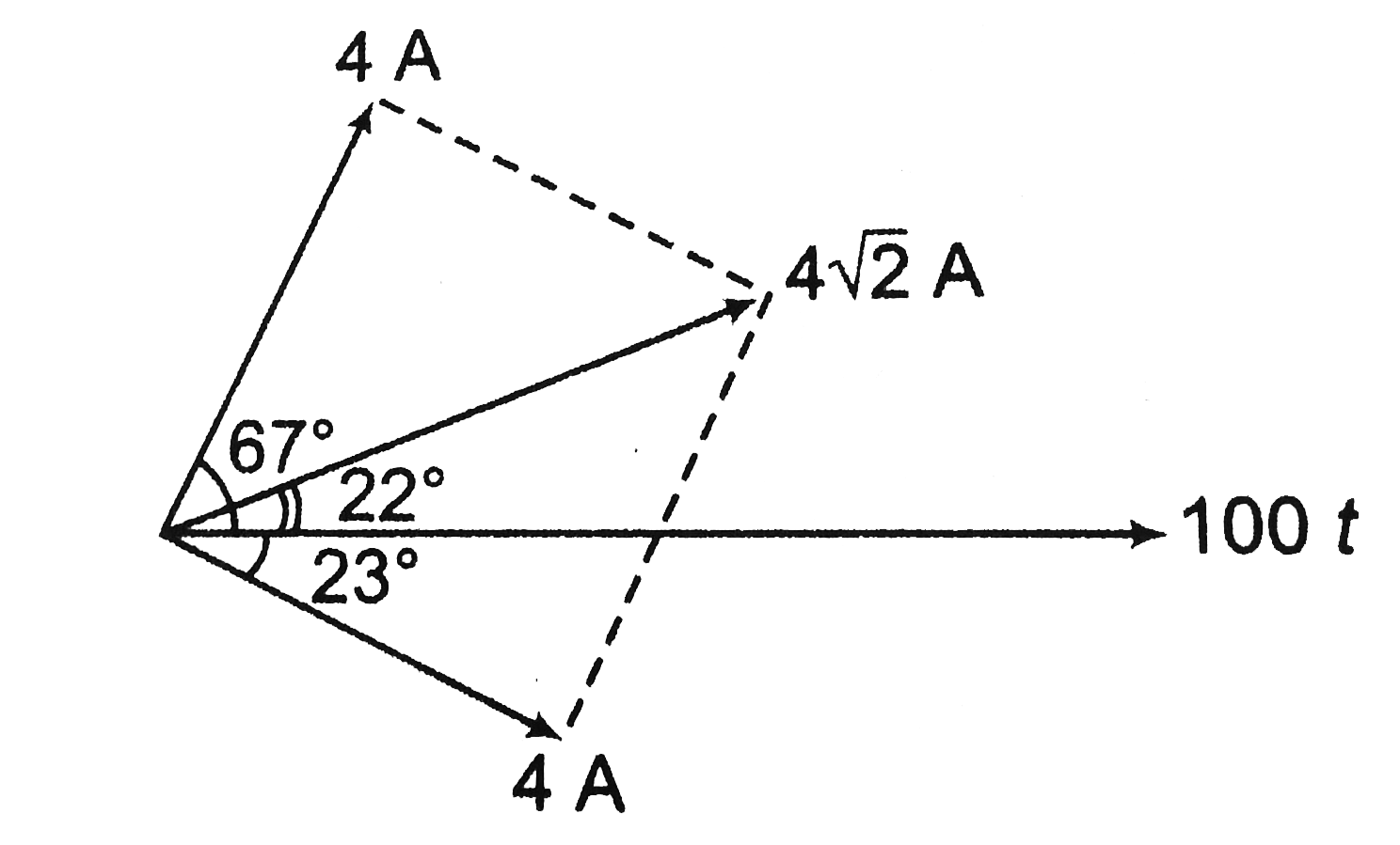
Resultant of 4A and 4A at 90∘ is 4√2 at 45∘ from both currents or at 22∘ from 100 t line
I=4√2sin(100t+22∘).
Topper's Solved these Questions
- ALTERNATING CURRENTBOOK - DC PANDEY ENGLISHCHAPTER - ALTERNATING CURRENTEXERCISE - Miscellaneous Examples
6 Videos
- ALTERNATING CURRENTBOOK - DC PANDEY ENGLISHCHAPTER - ALTERNATING CURRENTEXERCISE - Exercise 28.1
3 Videos
- ALTERNATING CURRENTBOOK - DC PANDEY ENGLISHCHAPTER - ALTERNATING CURRENTEXERCISE - Example Type 2
1 Video
- ATOMSBOOK - DC PANDEY ENGLISHCHAPTER - ATOMSEXERCISE - MEDICAL ENTRANCES GALLERY
42 Videos
Similar Questions
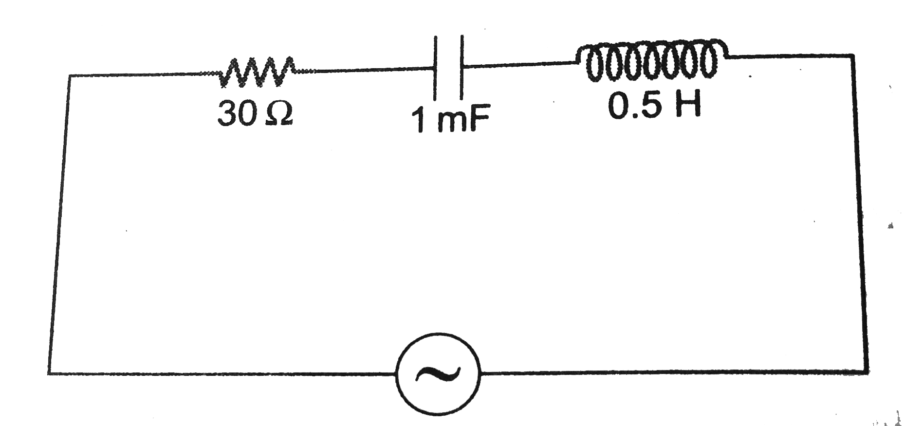
In the diagram shown in figure, V function is given. Find other four functions of time I,VC,VR and VL. Also, find power consumed in the circuit, V is given in volts and ω in rad/s.
View SolutionIn the circuit shown in figure
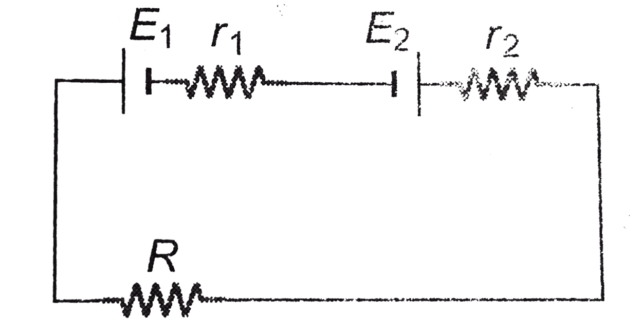
E1=10V,E2=4V,r1=r2=1Ω and R=2Ω.
Find the potential difference across battery 1 and battery 2.
View SolutionIn the circuit shown in figure

E1=10V,E2=4V,r1=r2=1Ω and R=2Ω.
Find the potential difference across battery 1 and battery 2.
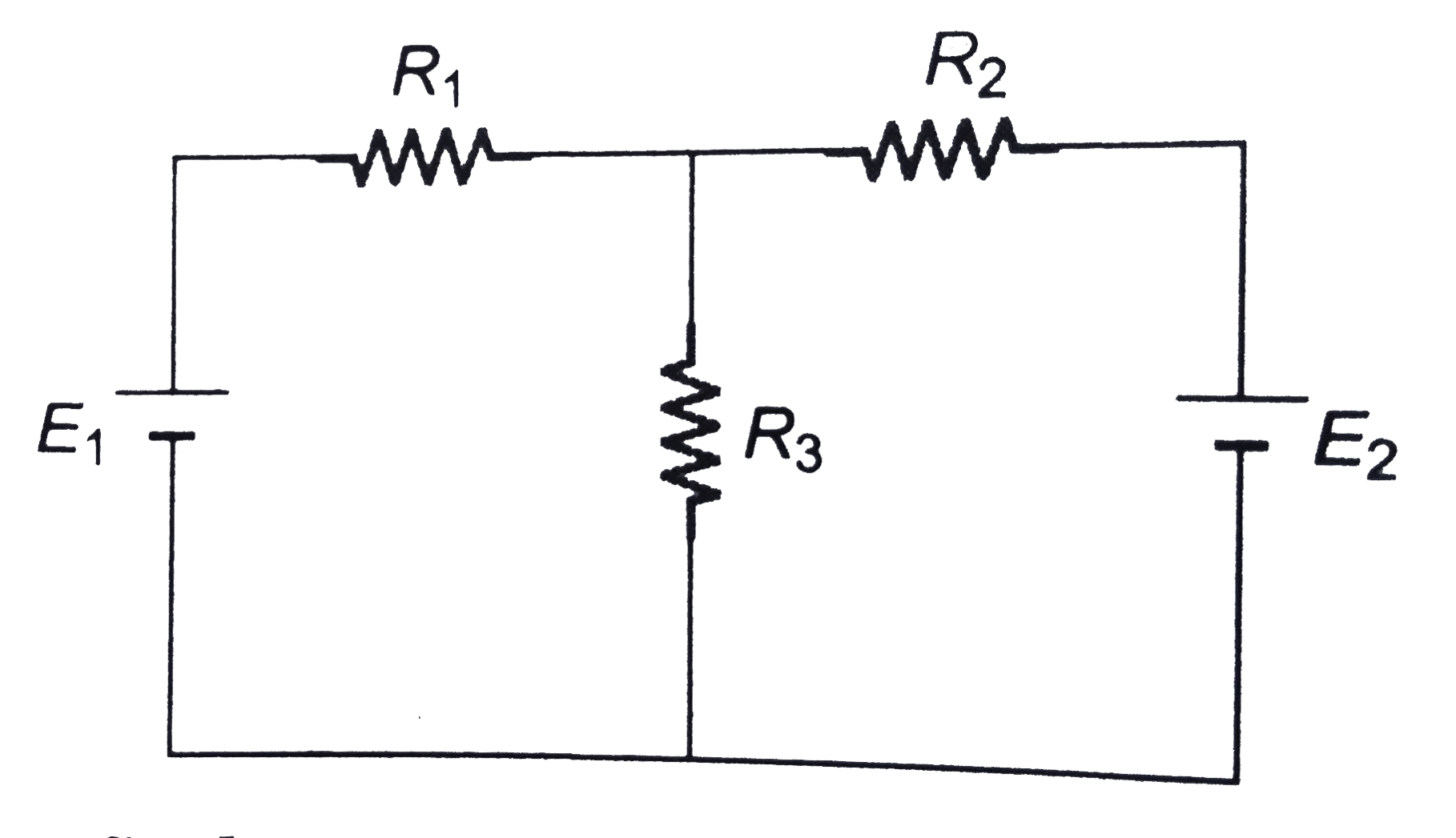
View SolutionIn the circuit shown in figure E1=7V,E2=1V,R1=2Ω,R2=2Ω and R3=3Ω respectively. Find the power supplied by the two batteries.
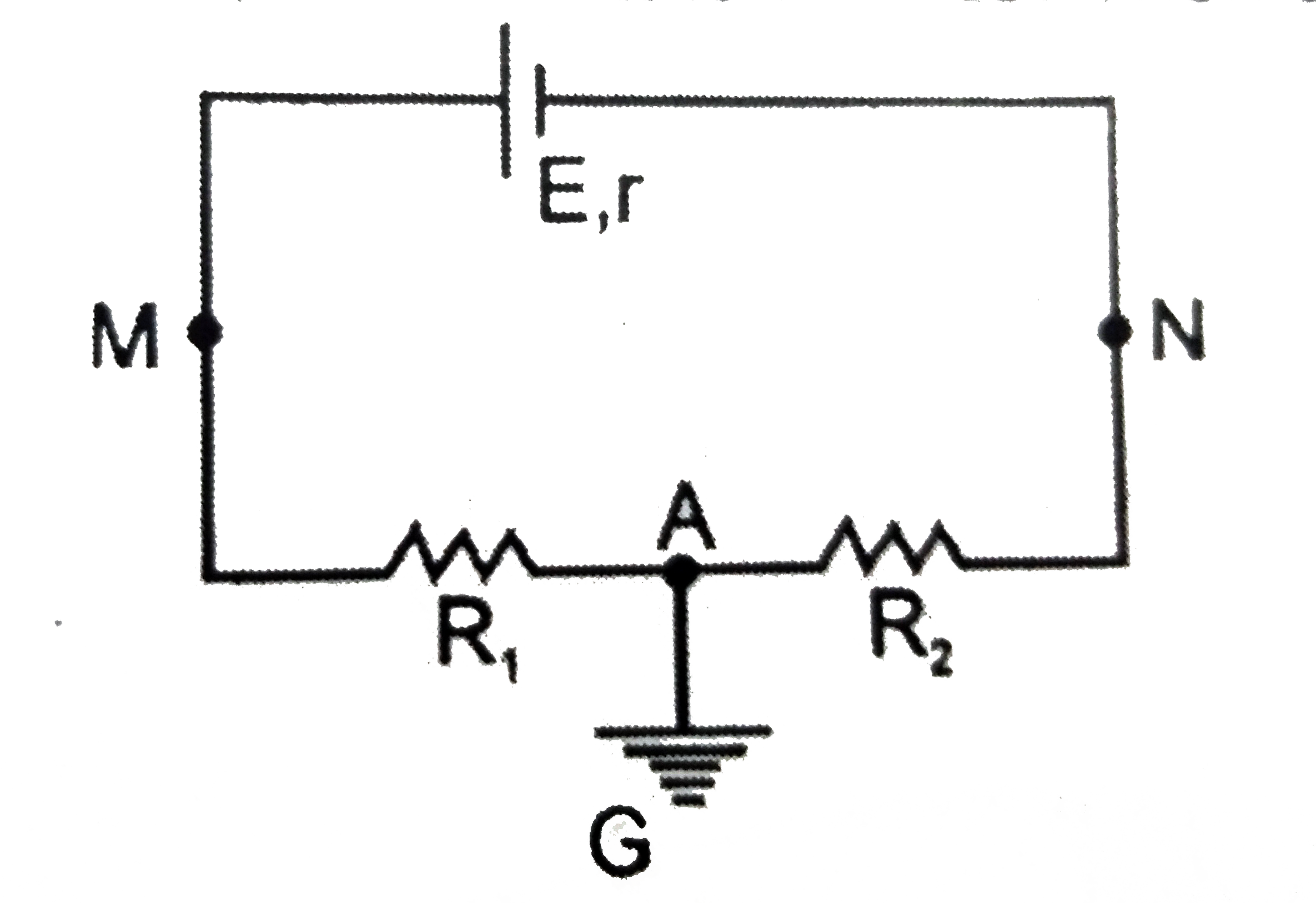
View SolutionIn the given figure, E=12V, R1=3Ω,R2=2Ω and r=1Ω. The choose the correct option/s
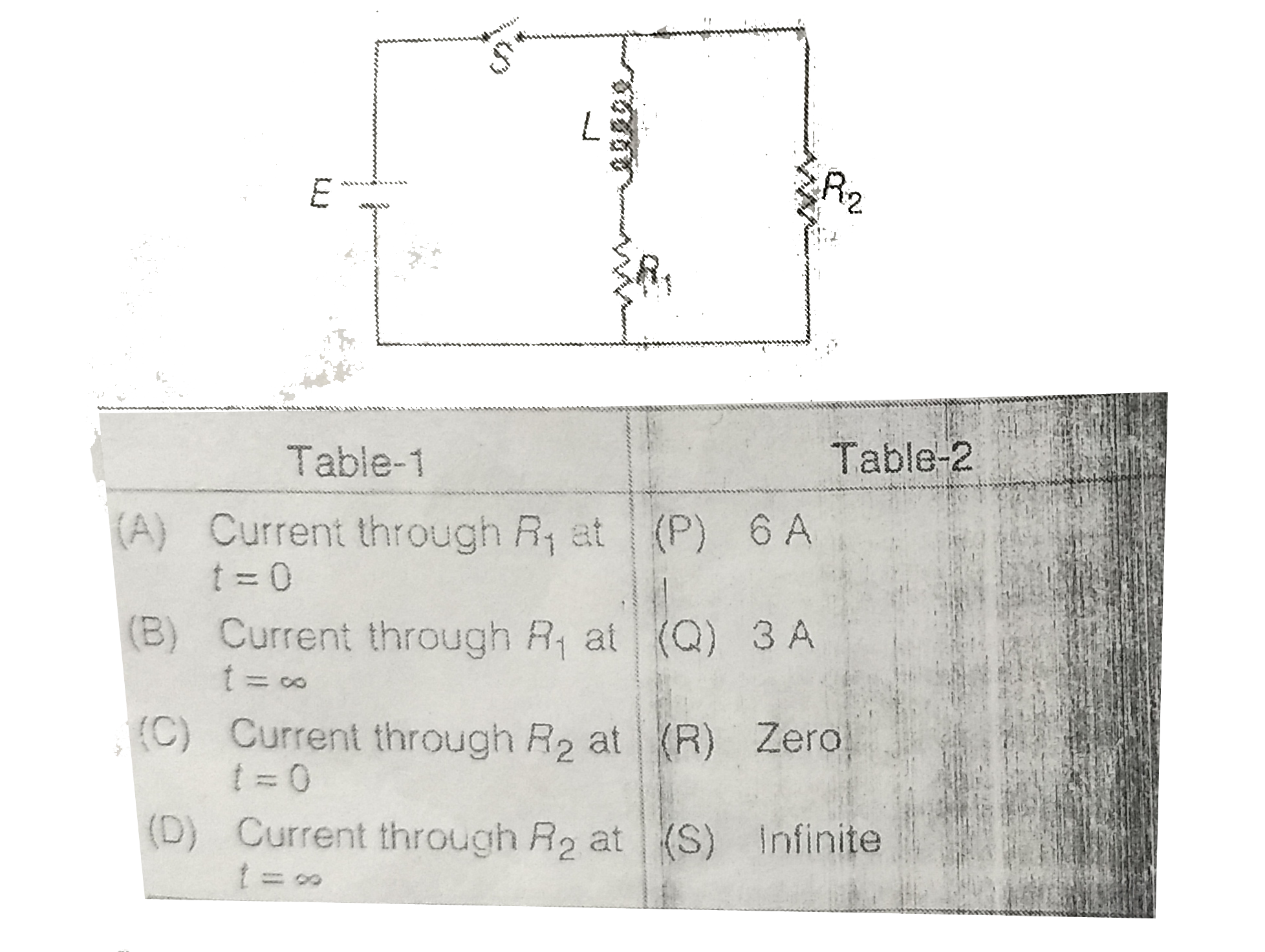
View SolutionIn the circuit diagram shown in Figure E=18V , L=2H, R1=3Ω,R2=6Ω. Switch S is closed at t=0 Match the following:
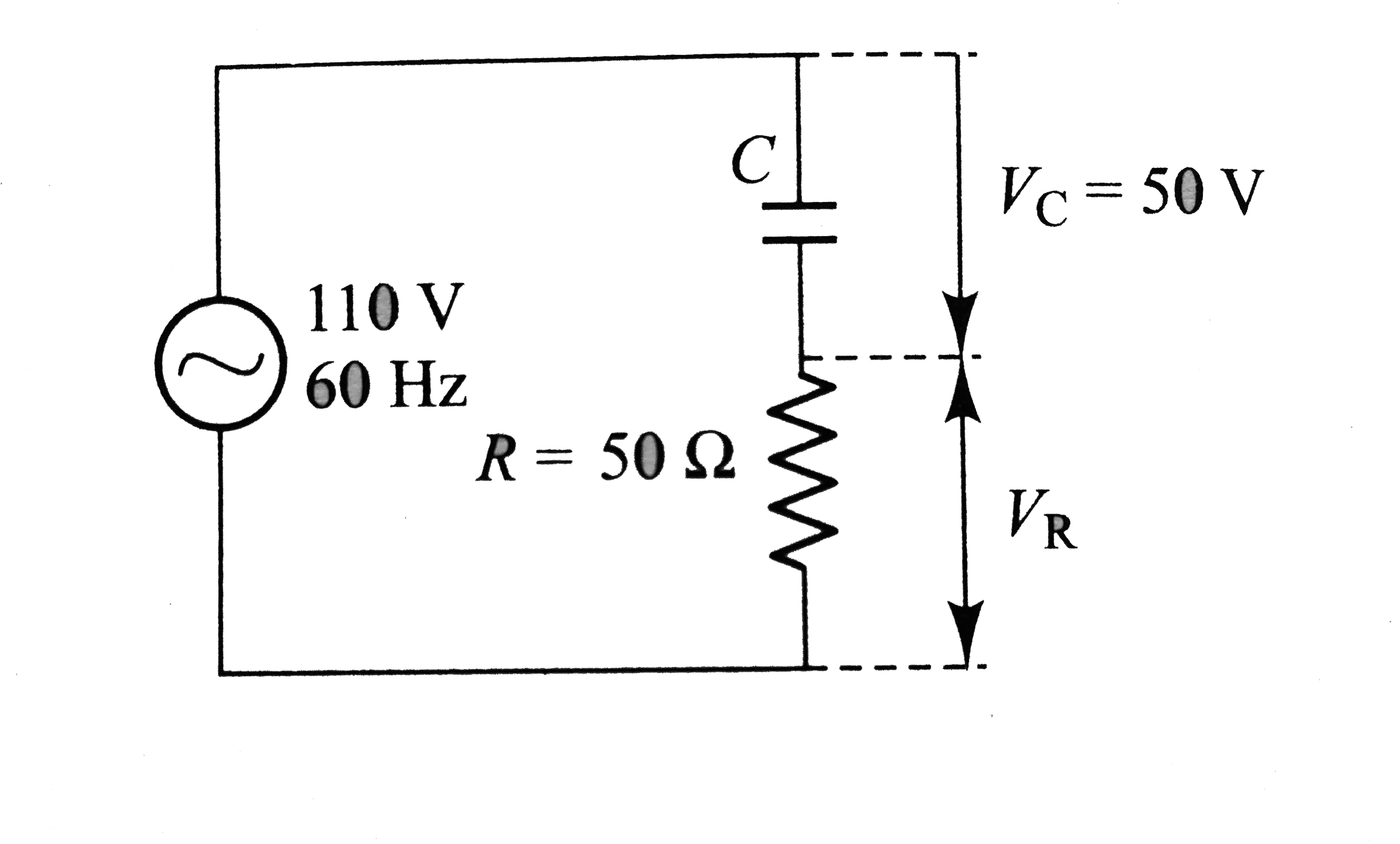
View SolutionIn the circuit given in fig. (VC)=50VandR=50Ω. The values of C and (VR) are
View Solution

In the circuit shown in figure. ε1=3,ε2=2,ε3=6V,R1=2,R4=6Ω,R3=2,R2=4ΩandC=5μF. Find the current in the resistor R3 and the electrical energy stored in the capacitor C.
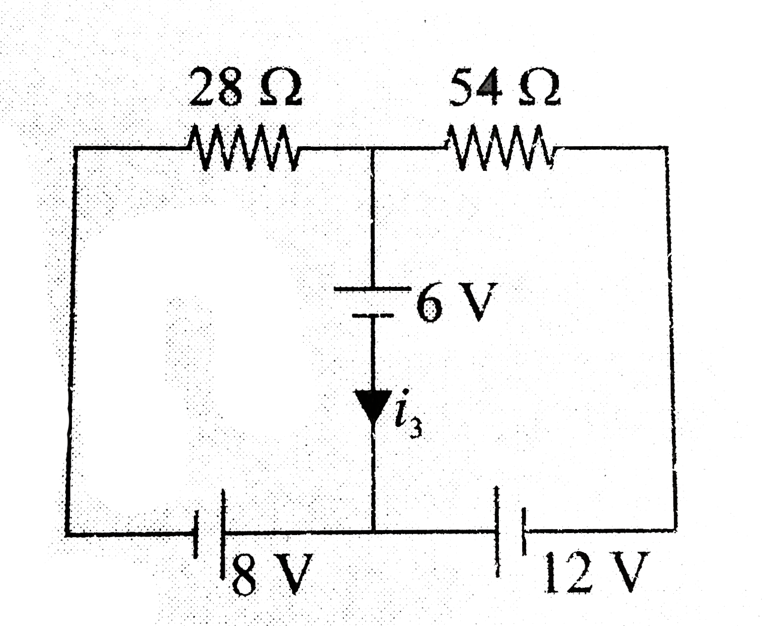
View SolutionIn the following circuit ,E1=4V,R1=2Ω,
E2=6V,R2=2Ω,andR3=4Ω. Find the currents i1andi2
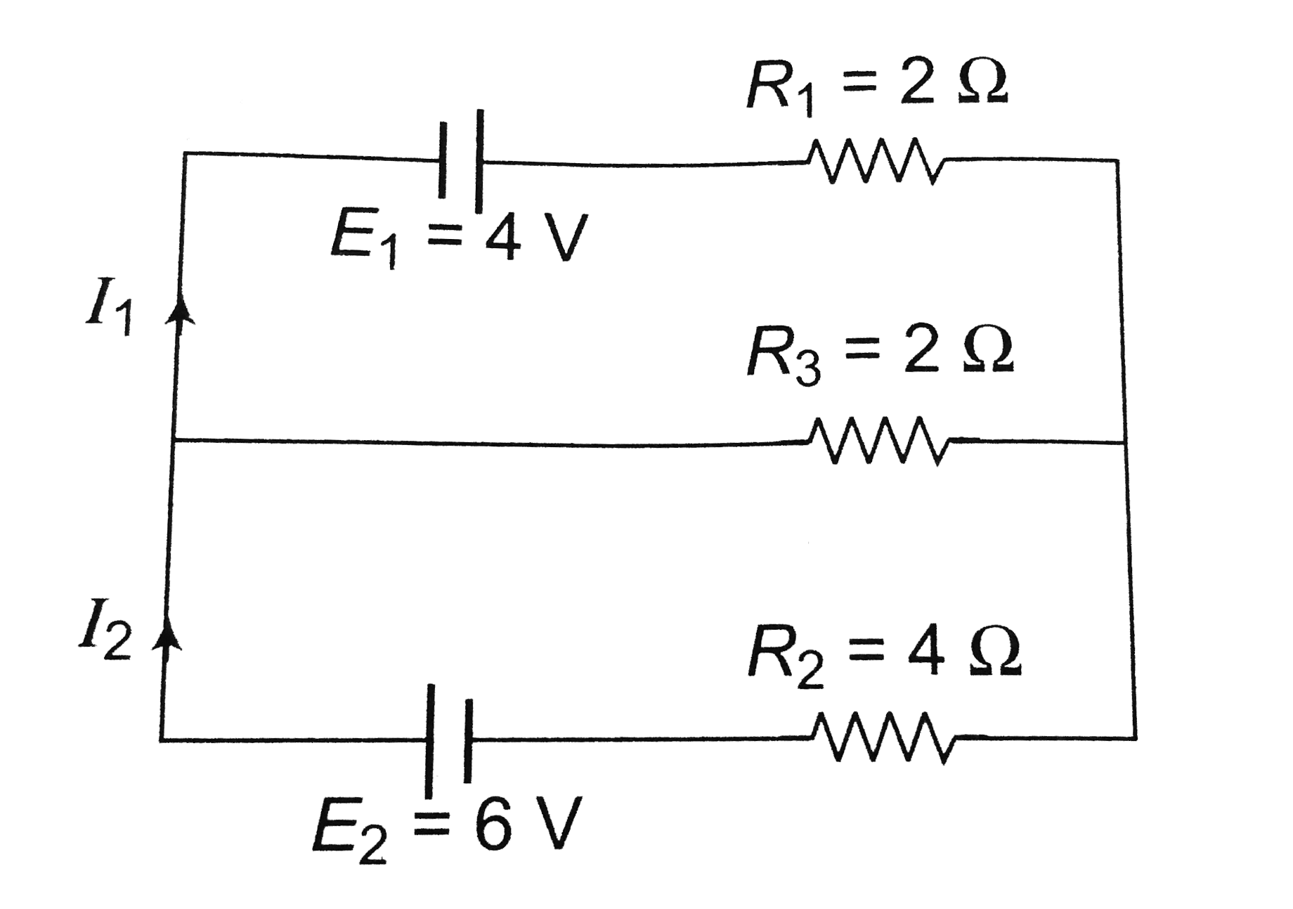
View SolutionIn the circuit shown below E1=4.0V,R1=2Ω,E2=6.0V,R2=4Ω and R3=2Ω. The current I1 is
View Solution
