When the switch S is closed at t=0, identify the correct statement just after closing the switch as shown in figure
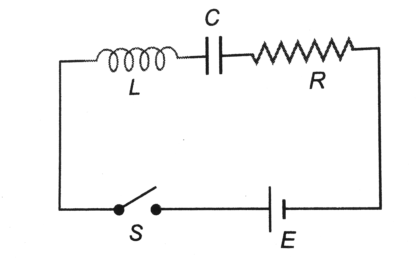
a) the current in the circuit is maximum
b) equal and opposite voltages are dropped across inductor and resistor
c) the entire voltage is dropped across inductor
d) All of the above
The correct Answer is:C
At t=0, VL=−E
Topper's Solved these Questions
- ELECTROMAGNETIC INDUCTIONBOOK - DC PANDEY ENGLISHCHAPTER - ELECTROMAGNETIC INDUCTIONEXERCISE - Level 2 More Than One Correct
10 Videos
- ELECTROMAGNETIC INDUCTIONBOOK - DC PANDEY ENGLISHCHAPTER - ELECTROMAGNETIC INDUCTIONEXERCISE - Level 2 Comprehension Based
13 Videos
- ELECTROMAGNETIC INDUCTIONBOOK - DC PANDEY ENGLISHCHAPTER - ELECTROMAGNETIC INDUCTIONEXERCISE - Level 1 Subjective
21 Videos
- CURRENT ELECTRICITYBOOK - DC PANDEY ENGLISHCHAPTER - CURRENT ELECTRICITYEXERCISE - Medical entrances gallery
97 Videos
- ELECTROMAGNETIC WAVESBOOK - DC PANDEY ENGLISHCHAPTER - ELECTROMAGNETIC WAVESEXERCISE - Sec C
22 Videos
Similar Questions
In the given circuit, the switch S is closed at time t=0 then select the correct statement for current l in resistance PQ as shown in the figure
_PHY_E05_091_Q01.png)
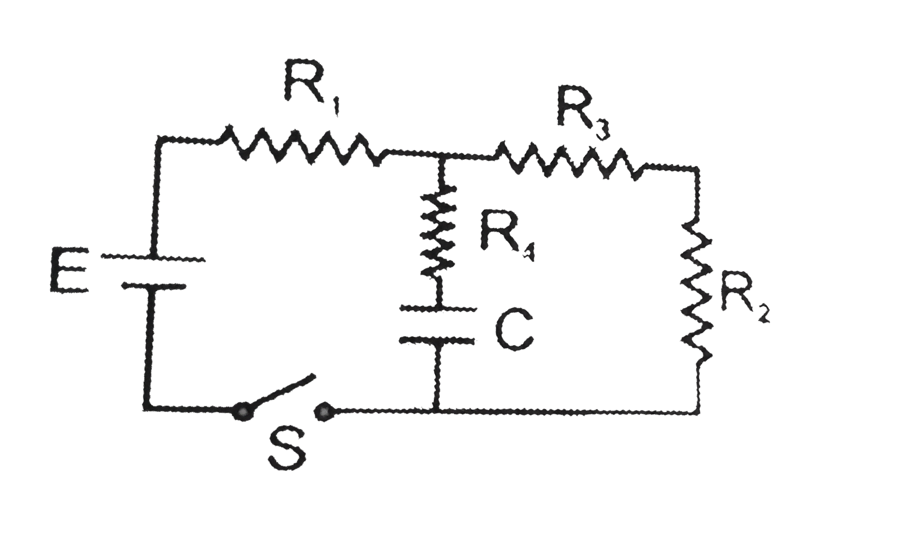
View SolutionIn the circuit shown in figure the switch S is closed at t = 0. A long time after closing the switch
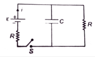
View SolutionIn the circuit shown, the switch is closed at t=0. Select the correct alternative(s)
View Solution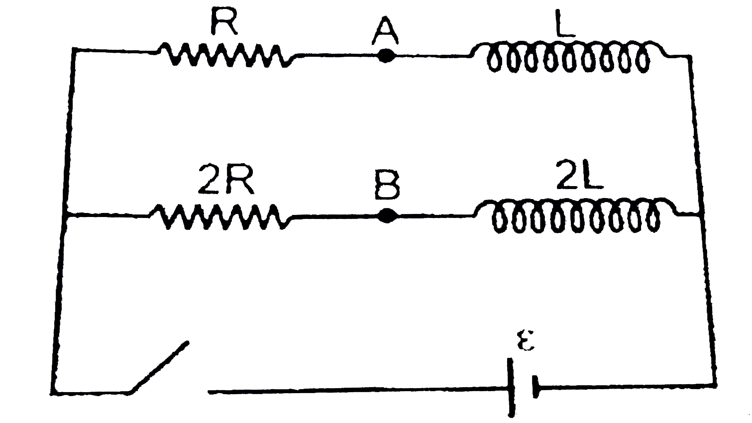
In given LR circuit the switch S is closed at time t=0 then
View SolutionSwitch S is closed at time t=0. Which one of the following statements is correct?
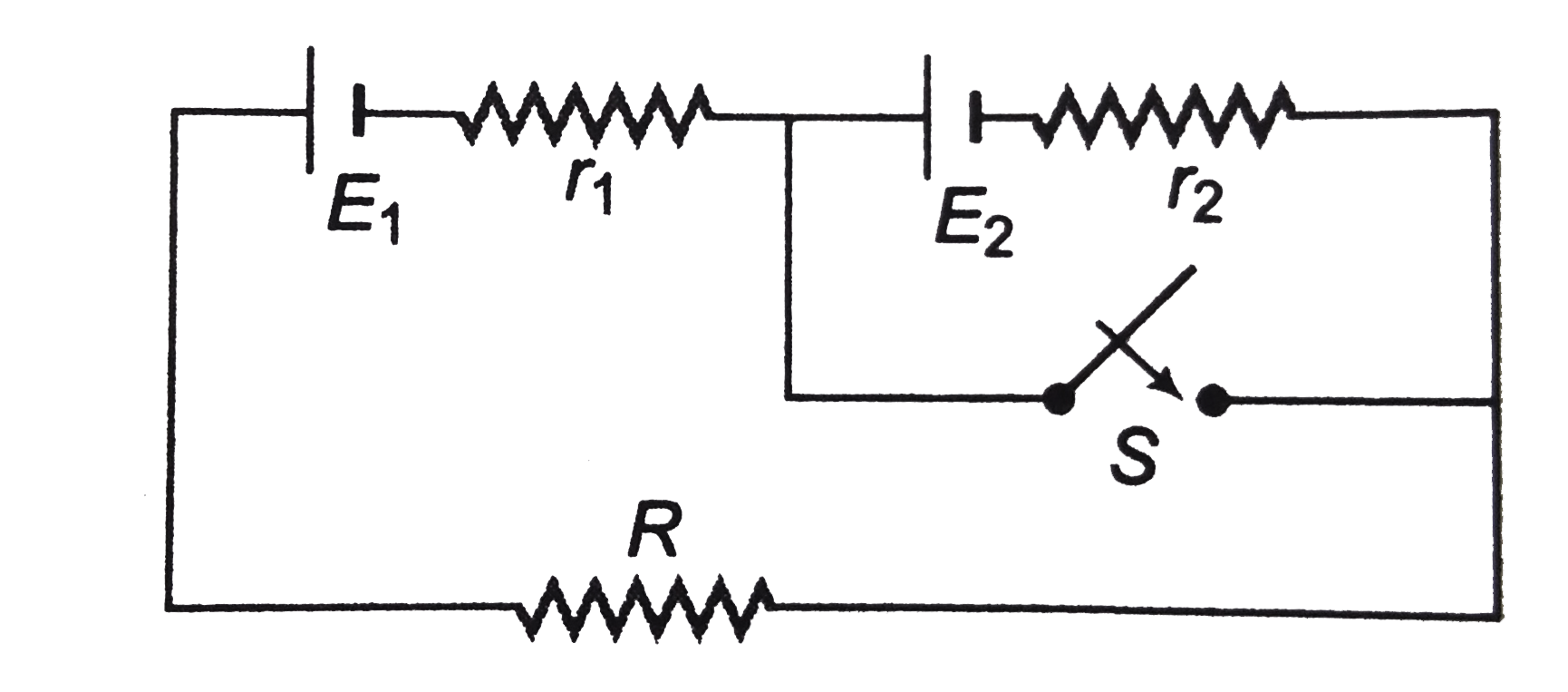
View SolutionIn the given circuit Fig the switch is closed at t=0. Choose the correct answers.
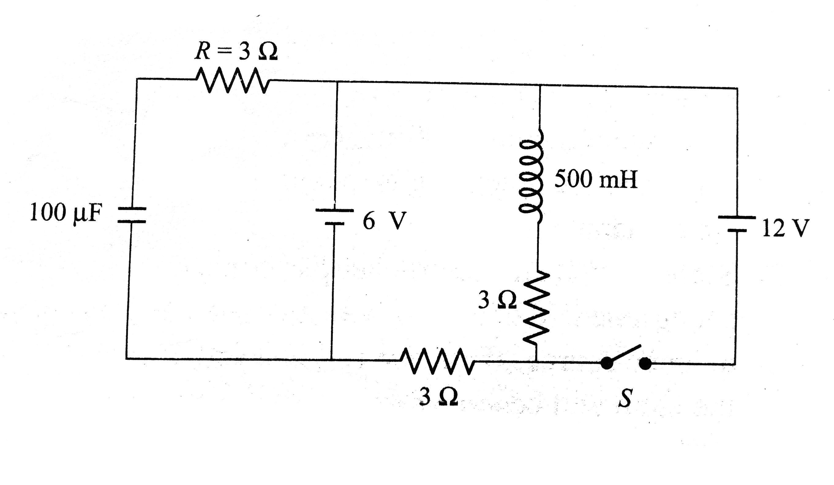
View SolutionIn the circuit shown in the figure, switch S is closed at time t=0. Select the correct statements.
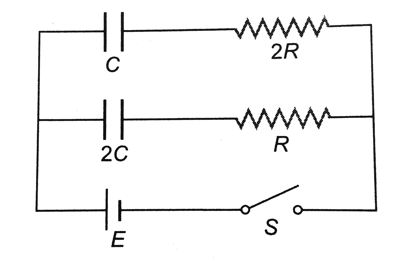
View SolutionIn the circuit shown in the figure, switch S is closed at time t=0. Select the correct statements.

View SolutionIn the circuit shown in figure switch S is closed at time t=0, which statement is true after one time constant of L-R circuit?
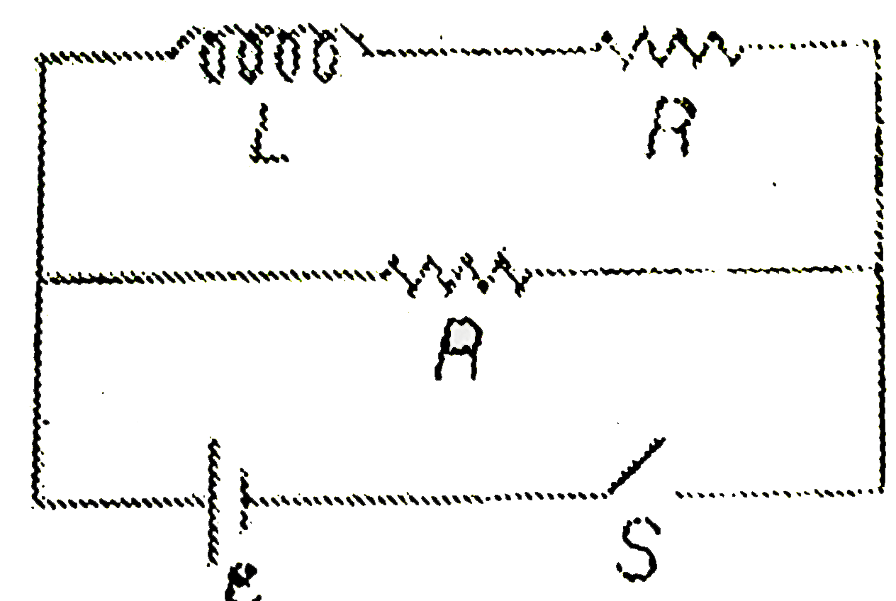
View SolutionIn the connection shown in the figure, initially the switch K is open and the capacitor is uncharged. Then the switch is closed, and the capacitor is charged up to the steady state and the switch is opened again. Determine the values indicated by the values indicated by the ammeter just after closing the switch
[GivenV0=30V,R1=10kΩ,R2=5kΩ]
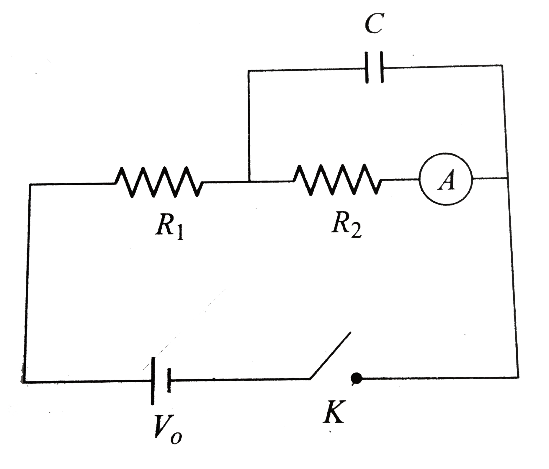 .
.
A long time after switch was closed.
View Solution
