In the circuit shown in figure find Vab at 1s 
Charge on capacitor is increasing. So, there is a current in the circuit from right to left. This current is given by
i=dqdt=2A
At 1s,q=2C
So, at 1s, circuit is as shown in figure 
Va+22(2)(4)+10=Vb
Va−Vb
or Vab=−19volt.
Topper's Solved these Questions
- CAPACITORSBook:DC PANDEY ENGLISHChapter:CAPACITORSExercise:Exercise
Explore 155 Videos
- CAPACITORSBook:DC PANDEY ENGLISHChapter:CAPACITORSExercise:OBJECTIVE_TYPE
Explore 1 Video
- ATOMSBook:DC PANDEY ENGLISHChapter:ATOMSExercise:MEDICAL ENTRANCES GALLERY
Explore 42 Videos
- COMMUNICATION SYSTEMBook:DC PANDEY ENGLISHChapter:COMMUNICATION SYSTEMExercise:Subjective
Explore 11 Videos
Similar Questions
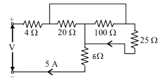
In the circuit shown in figure , V must be
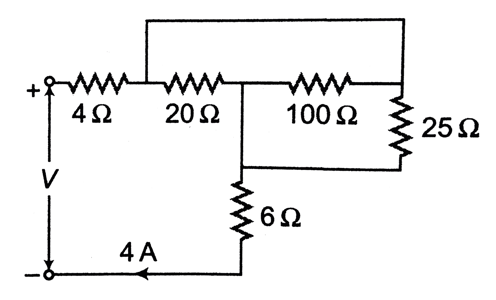
View SolutionIn the circuit shown in figure , V must be

View SolutionIn the circuit shown in figure value of VR is
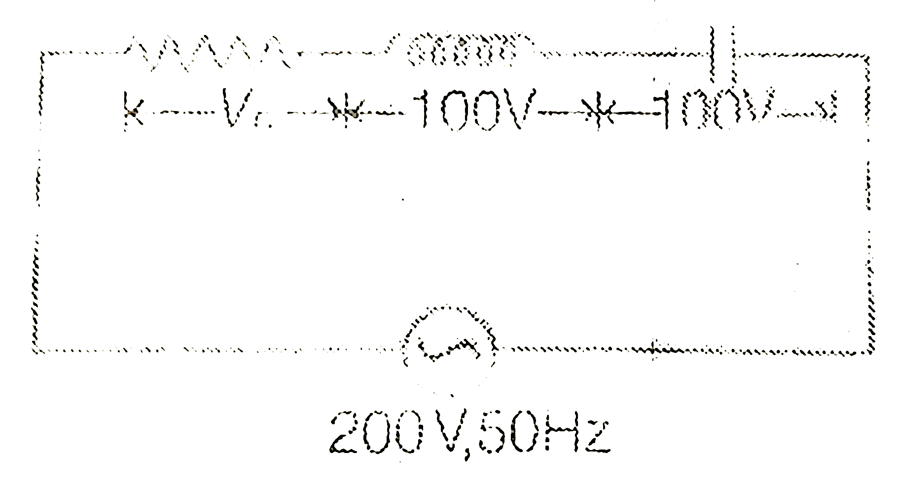
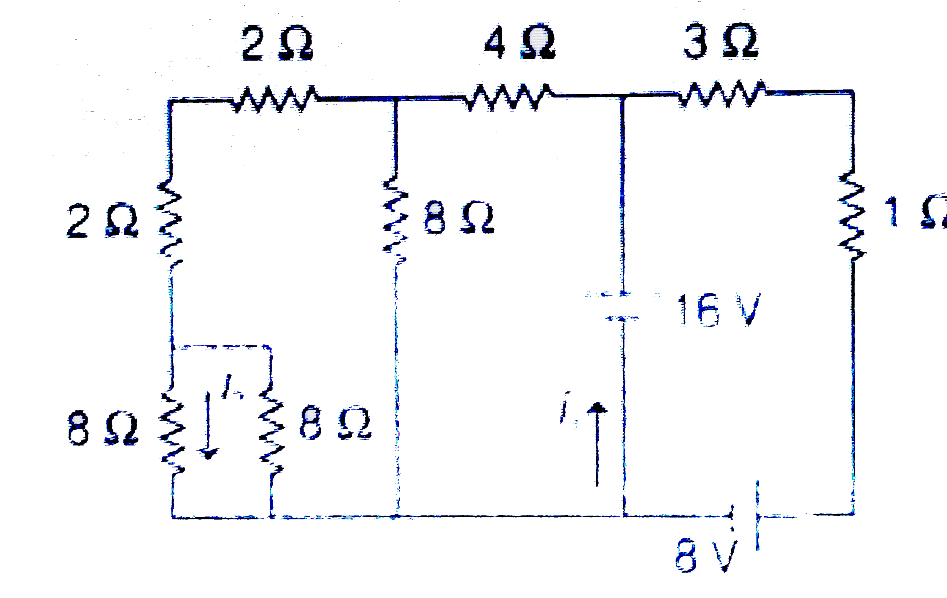
View SolutionIn the circuit shown in figure ,find the ratio of currents i1/i2.
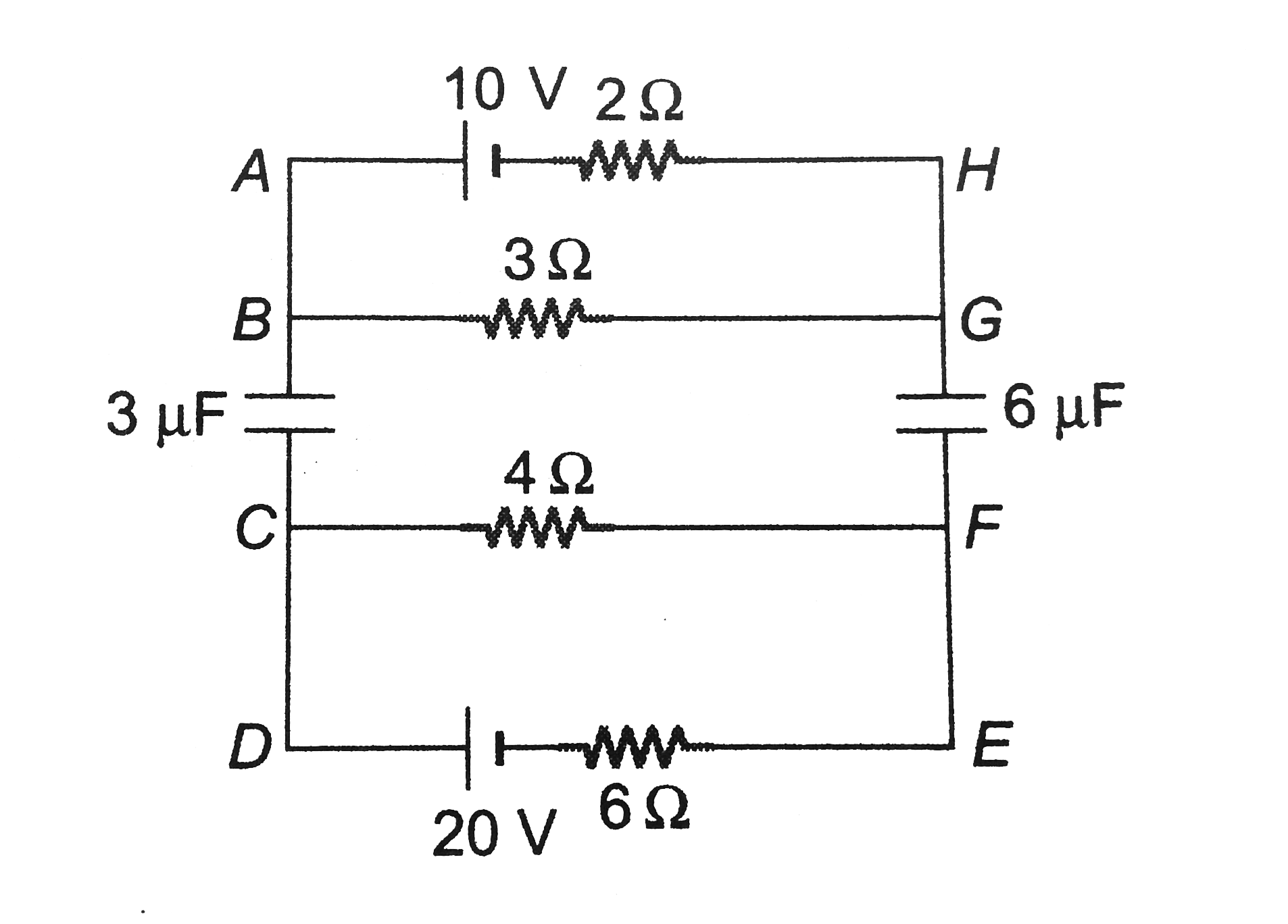
View SolutionIn the circuit shown in figure, find the steady state charges on oth the capacitors.
View SolutionIn the circuit shown in the figure , V must be -
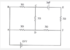
View SolutionIn the circuit shown in the figure, find the total resistance of the circuit and current in CD arm.
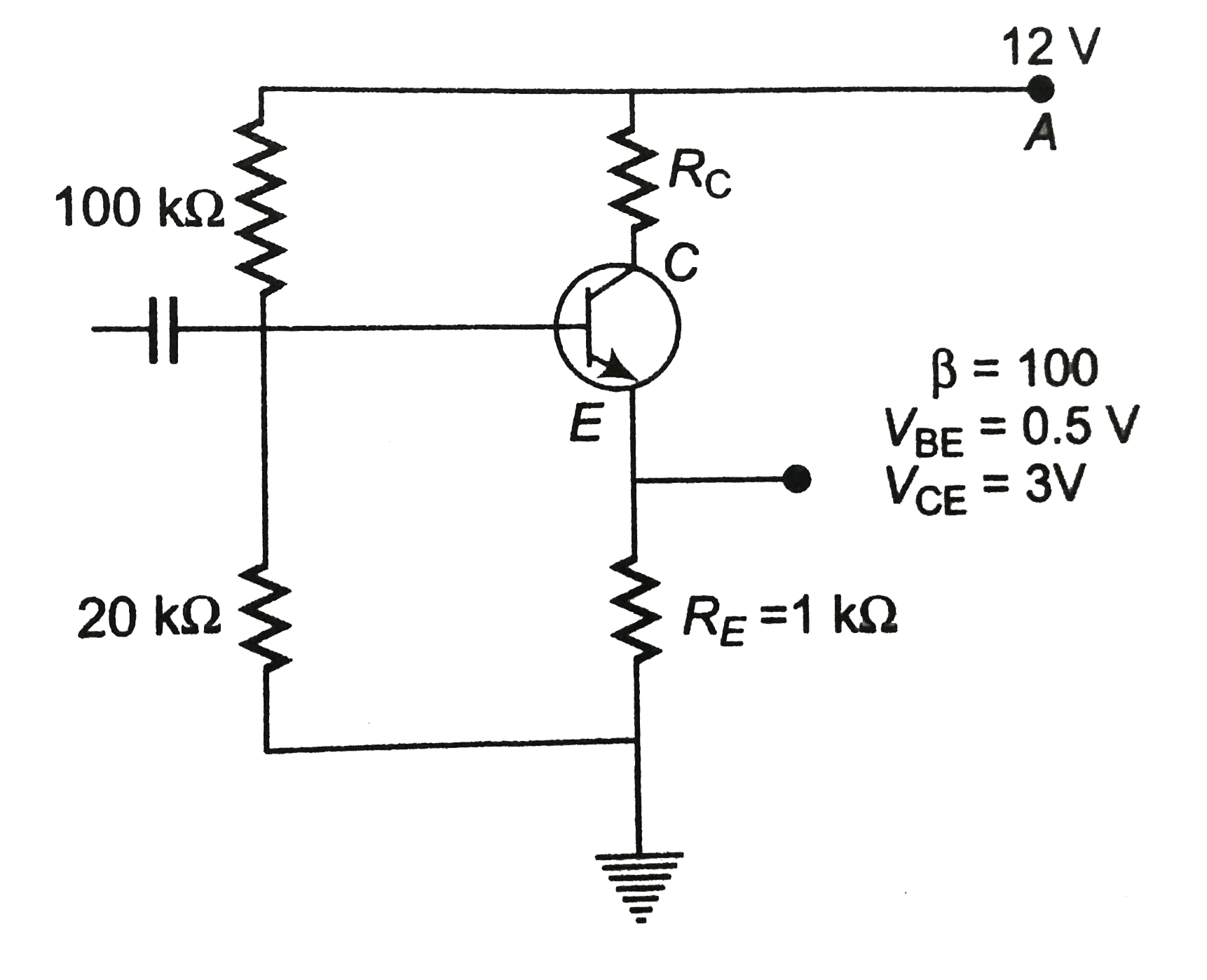
View SolutionIn the circuit shown in figure , find the value of RC.
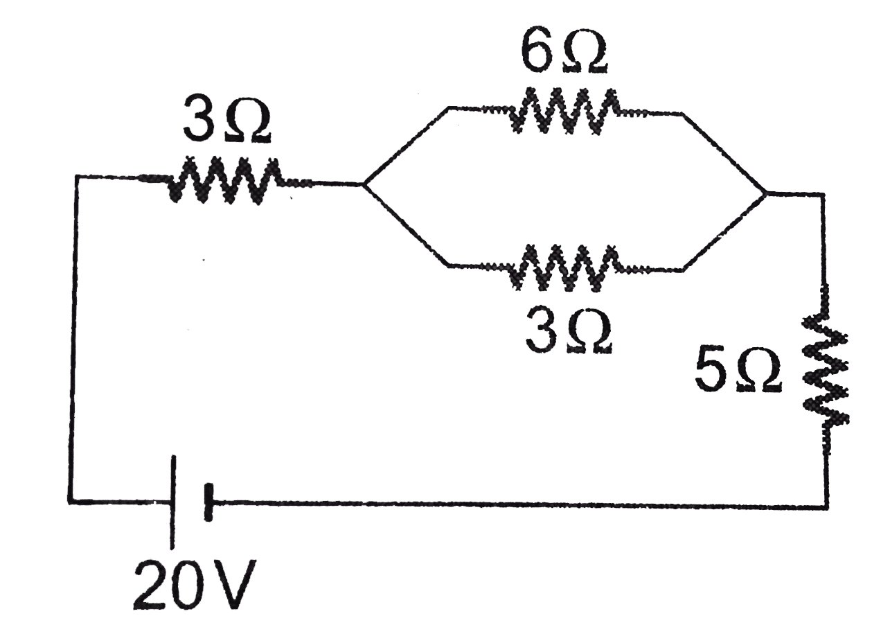
View SolutionIn the circuit shown in figure find the heat developed across each resistance in 2s.
View SolutionIn the circuit shown in figure ,
a. find the current is each branch
b. find the potential difference Vab of point a relative to point b.
View Solution

