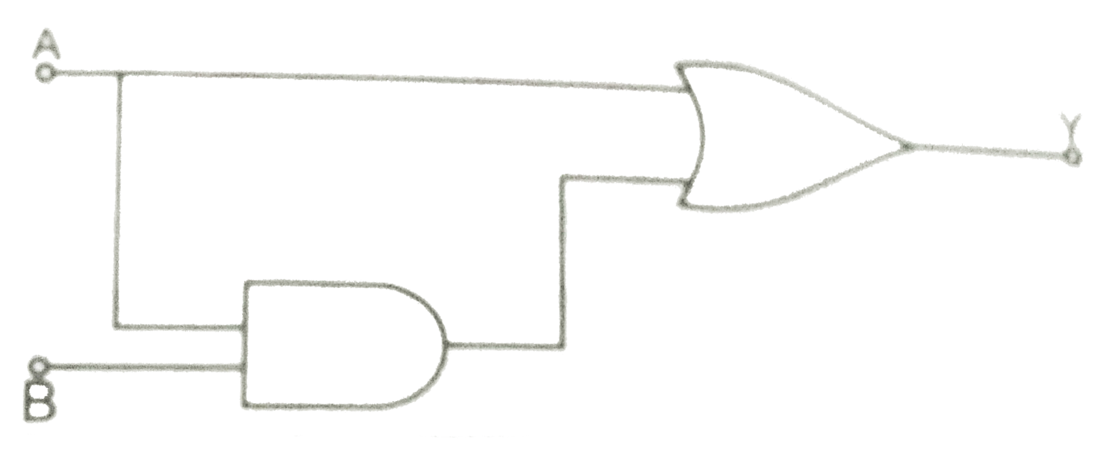
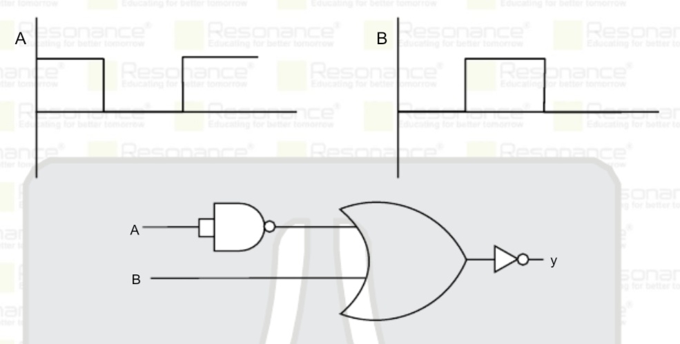
The following inputs are given to following circuit
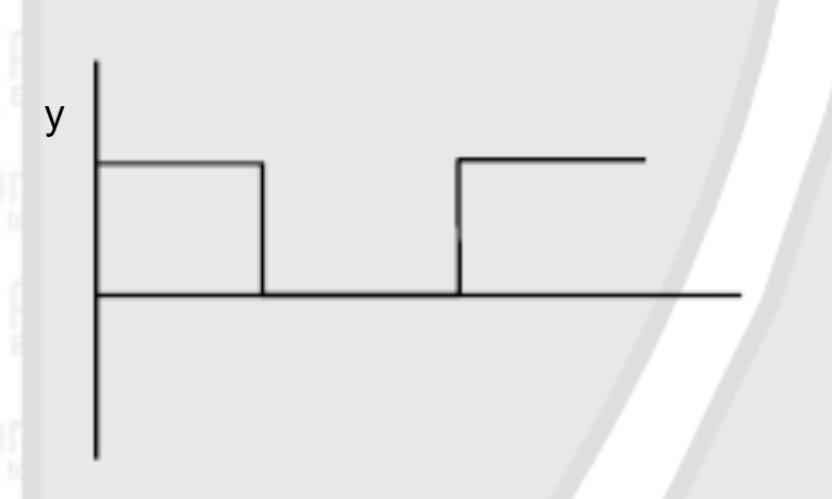
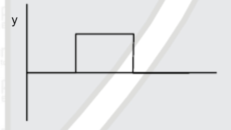
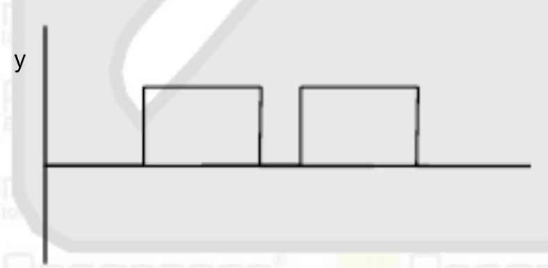
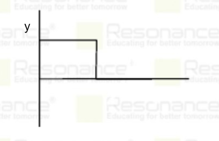
The correct Answer is:A
Step by step video, text & image solution for The following inputs are given to following circuit by Physics experts to help you in doubts & scoring excellent marks in Class 12 exams.
Topper's Solved these Questions
- BOOK - JEE MAINS PREVIOUS YEARCHAPTER - JEE MAIN 2021EXERCISE - SECTION-A80videos
JEE MAIN 2021
- BOOK - JEE MAINS PREVIOUS YEARCHAPTER - JEE MAIN 2021EXERCISE - SECTION-B40videos
JEE MAIN 2021
- BOOK - JEE MAINS PREVIOUS YEARCHAPTER - JEE MAINEXERCISE - All Questions473videos
JEE MAIN
- BOOK - JEE MAINS PREVIOUS YEARCHAPTER - JEE MAIN 2022EXERCISE - Question492videos
JEE MAIN 2022
Similar Questions
Knowledge Check
- Question 1 - Select One
Assertion: De Morgan's theoram ¯¯¯¯¯¯¯¯¯¯¯A+B=¯¯¯A.¯¯¯B may be explained by the following circuit.
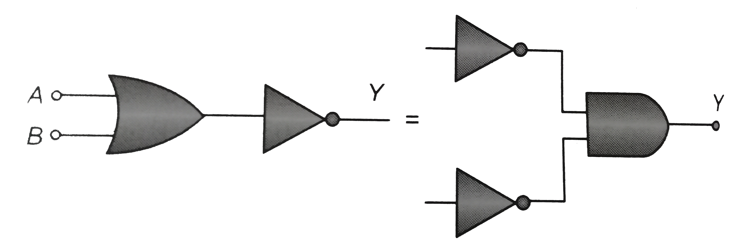
Reason: In the following circuit, for output, inputs ABC are 101.
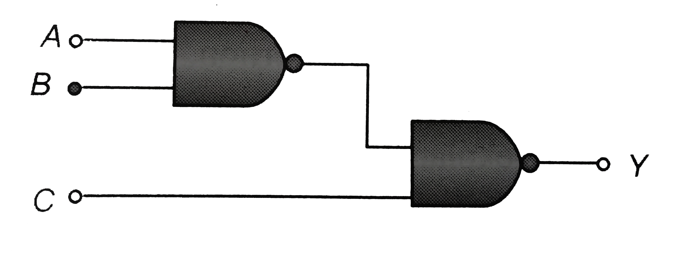 AIf both the assertion and reason are true and reason is a true explantion of the assertion.BIf both the assertion and reason are true but the reason is not true the correct explantion of the assertion.CIf the assertion is true but reason falseDIf both the assertion and reason are false.
 - Question 2 - Select One
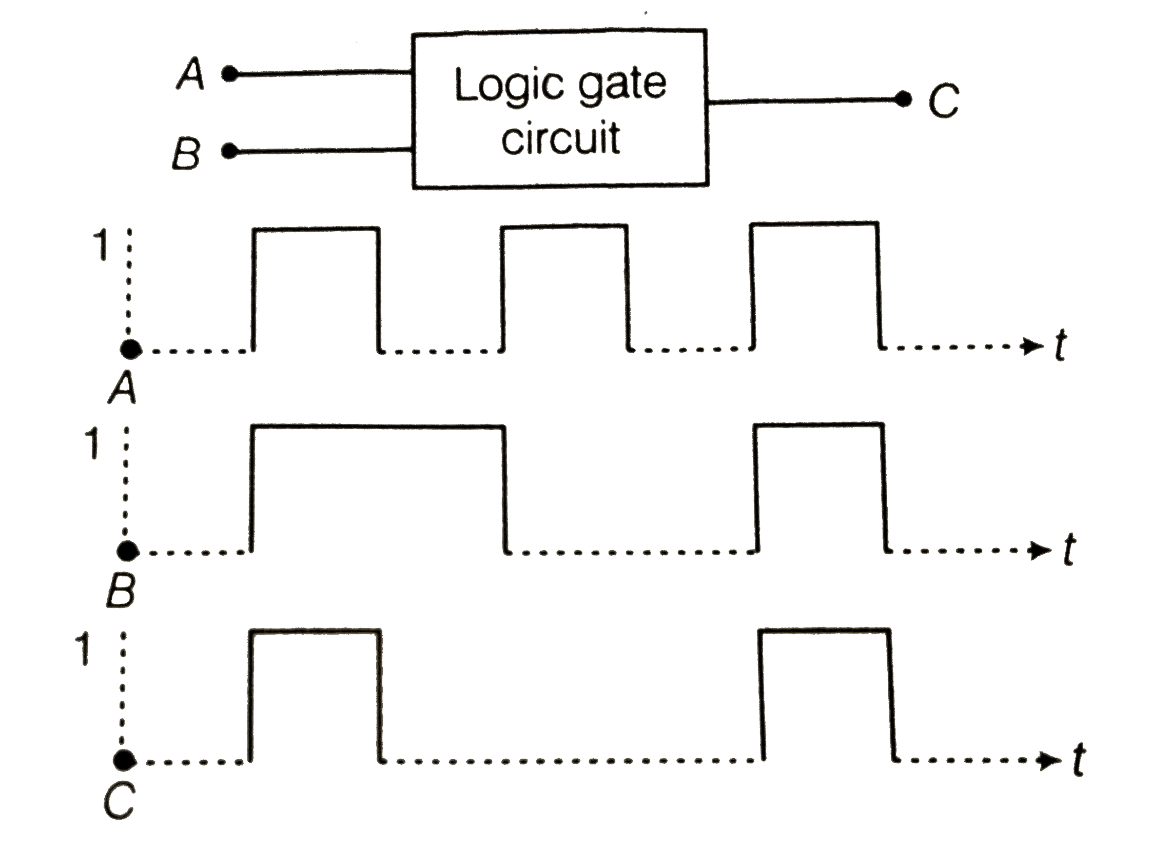
The following figure shown a logic gate circuit with ttwo inputs A and B and the C are as shown below
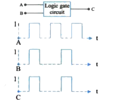
The logic circuit gate isAAND gateBNAND gateCNOR gateDOR gate - Question 3 - Select One
The following figure shows a logic gate circuit with two inputs A and B and the output Y. The voltage waveforms of A,B and the output Y are as given
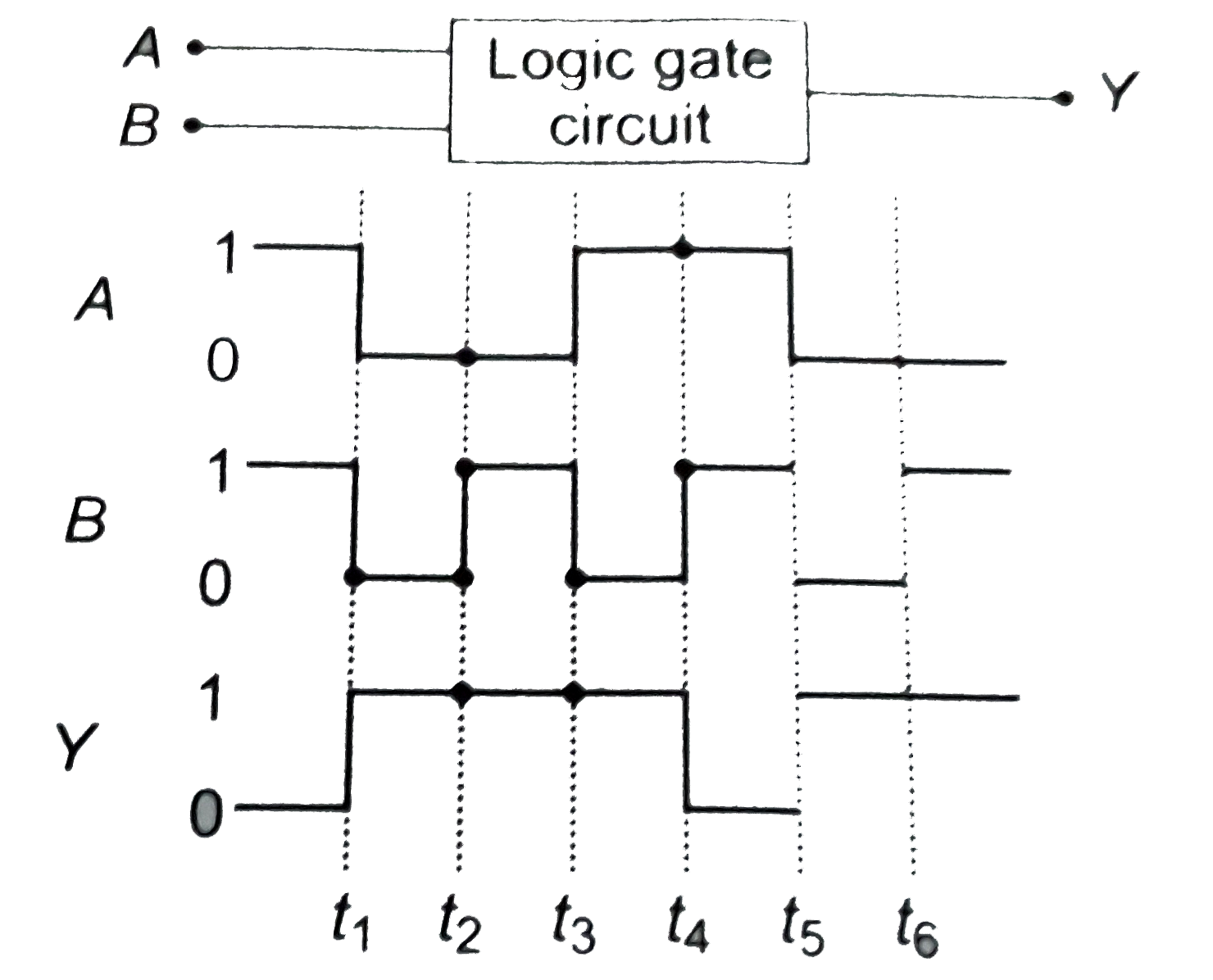 ANOR gateBOR gateCAND gateDNAND gate
The following figure shows a logic gate circuit with two inputs A and B and the output Y. The voltage waveforms of A,B and Y are as given :
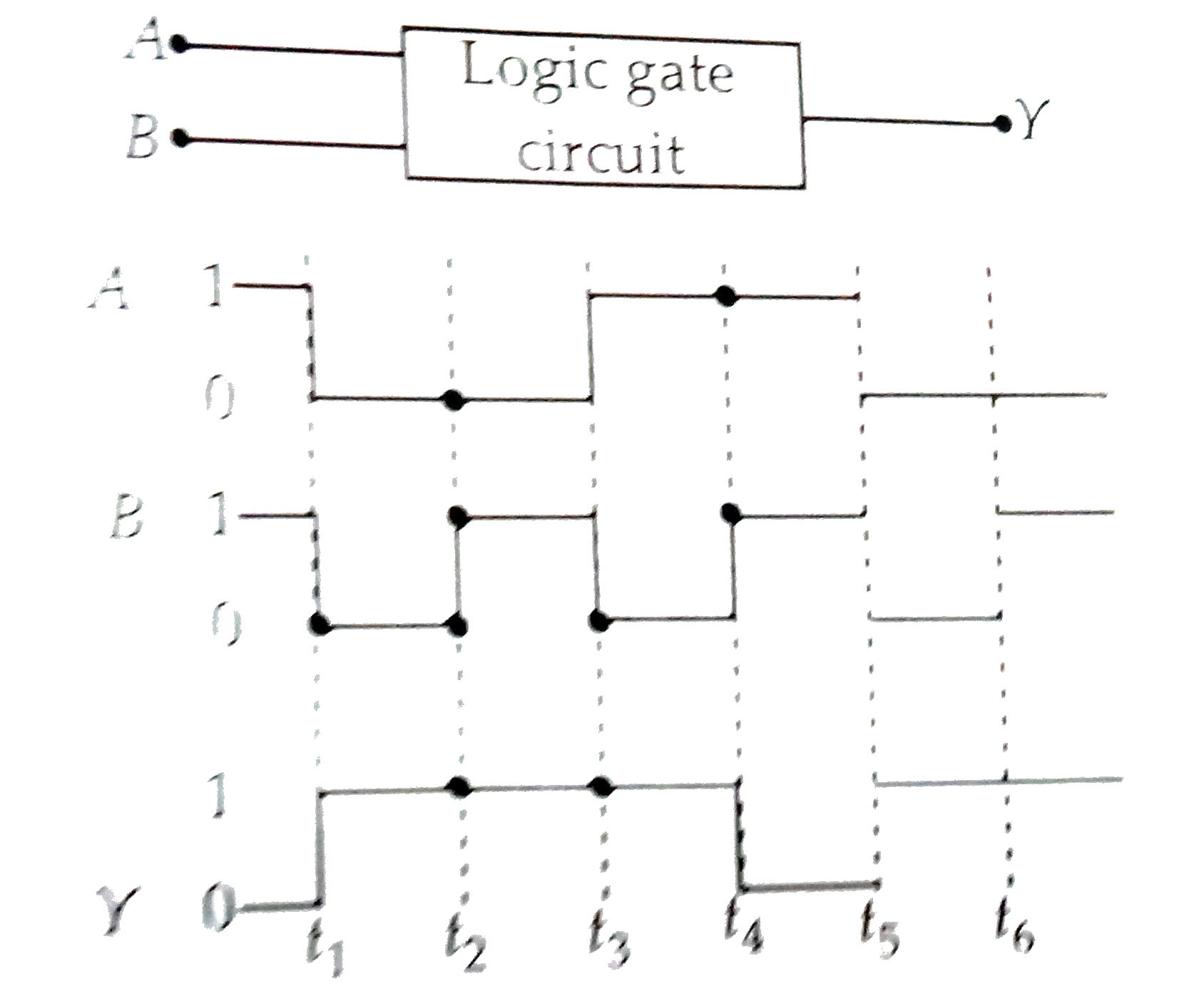
The logic gate isView SolutionThe following figure shows a logic gate circuit with two inputs A and B and the output Y. The voltage waveforms of A,B and the output Y are as given
 View Solution
The following figure shows a logic gate circuit with two inputs A and B output C. The voltage waveforms of A,B and C are as shown in second figure given below :-
_E01_436_Q01.png)
The logic circuit gate is :-View SolutionThe following figure shows a logic gate circuit with two inputs A and B and the output C. The voltage waveforms of A, B and C are as shown below
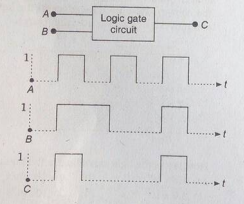
The logic circuit gate isView SolutionThe following figure shows a logic gate circuit with two inputs A and B and the output C. The voltage waveforms of A, B and C are as shown below

The logic circuit gate isView Solution


