An AND gate
is equivalent to a parallel switching current
is equivalent to a series switching current
has two outputs and one inputs
has two outputs and two inputs
The correct Answer is:B
Step-by-Step Solution:
1. Understanding the AND Gate:
- An AND gate is a basic logic gate that implements logical conjunction. It has two inputs, typically labeled A and B, and one output, labeled Y.
2. Output Condition:
- The output Y of an AND gate can be expressed mathematically as:
Y=A⋅B
- This means that the output Y will be high (1) only if both inputs A and B are high (1). If either input is low (0), the output will also be low (0).
3. Behavior of the AND Gate:
- The truth table for an AND gate is as follows:
| A | B | Y (Output) |
|---|---|------------|
| 0 | 0 | 0 |
| 0 | 1 | 0 |
| 1 | 0 | 0 |
| 1 | 1 | 1 |
- From this table, we can see that the output is only high when both inputs are high.
4. Circuit Representation:
- The circuit symbol for an AND gate is typically represented as a flat-ended shape with two inputs on the left and one output on the right.
5. Comparison with Series and Parallel Circuits:
- An AND gate can be compared to a series circuit. In a series circuit, the current flows only if all components are functioning (similar to both inputs being high).
- In contrast, a parallel circuit (like an OR gate) allows current to flow if at least one component is functioning (similar to any input being high).
6. Conclusion:
- Therefore, we conclude that an AND gate is equivalent to a series switching circuit. The correct answer is option B.
- An AND gate is a basic logic gate that implements logical conjunction. It has two inputs, typically labeled A and B, and one output, labeled Y.
- The output Y of an AND gate can be expressed mathematically as:
Y=A⋅B
- This means that the output Y will be high (1) only if both inputs A and B are high (1). If either input is low (0), the output will also be low (0).
- The truth table for an AND gate is as follows:
| A | B | Y (Output) |
|---|---|------------|
| 0 | 0 | 0 |
| 0 | 1 | 0 |
| 1 | 0 | 0 |
| 1 | 1 | 1 |
- From this table, we can see that the output is only high when both inputs are high.
- The circuit symbol for an AND gate is typically represented as a flat-ended shape with two inputs on the left and one output on the right.
- An AND gate can be compared to a series circuit. In a series circuit, the current flows only if all components are functioning (similar to both inputs being high).
- In contrast, a parallel circuit (like an OR gate) allows current to flow if at least one component is functioning (similar to any input being high).
- Therefore, we conclude that an AND gate is equivalent to a series switching circuit. The correct answer is option B.
Topper's Solved these Questions
- PRACTICE PAPPERBook:NCERT FINGERTPS ENGLISHChapter:PRACTICE PAPPERExercise:Practice Paper 1
Explore 50 Videos
- PRACTICE PAPPERBook:NCERT FINGERTPS ENGLISHChapter:PRACTICE PAPPERExercise:Practice Paper 2
Explore 50 Videos
- PRACTICE PAPPERBook:NCERT FINGERTPS ENGLISHChapter:PRACTICE PAPPERExercise:Practice Papper 2
Explore 50 Videos
- NUCLEIBook:NCERT FINGERTPS ENGLISHChapter:NUCLEIExercise:Assertion And Reason
Explore 15 Videos
- RAY OPTICS AND OPTICAL INSTRUMENTSBook:NCERT FINGERTPS ENGLISHChapter:RAY OPTICS AND OPTICAL INSTRUMENTSExercise:NCERT Exemplar
Explore 11 Videos
Similar Questions
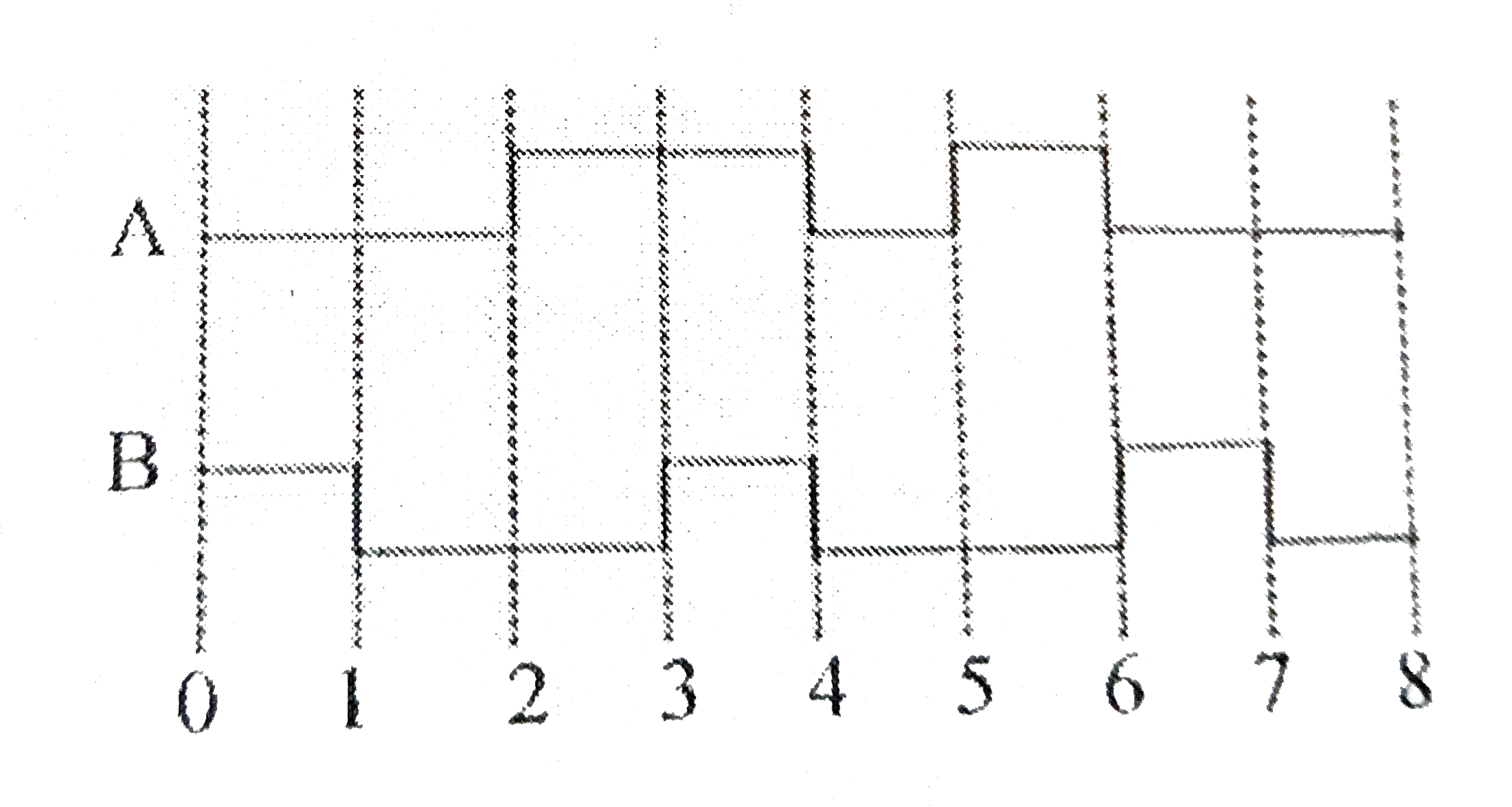
Draw the output wave from (Y) of the
(i) OR gate
(ii) NOR gate
(iii) AND gate (iv) NAND gate

View SolutionHow many NAND gates used to form AND gate.
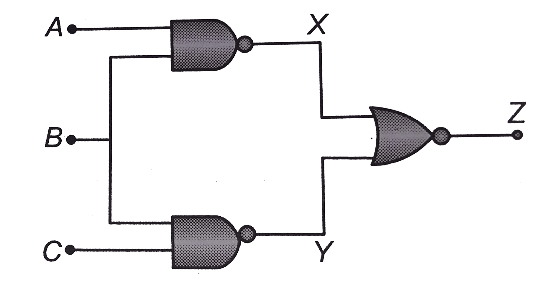
View SolutionThe figure shows two NAND gates followed by a NOR gate. The system is equivalent to the following logic gate

View SolutionThe minimum NOR gates are required to make one NAND gate are
View SolutionHow many minimum NAND gate are required to obtain NOR gate :-
View SolutionThe output of an OR gate is connected to both the inputs of a NAND gate. The combination will serve as a
View SolutionGive the logic symbol of AND gate.
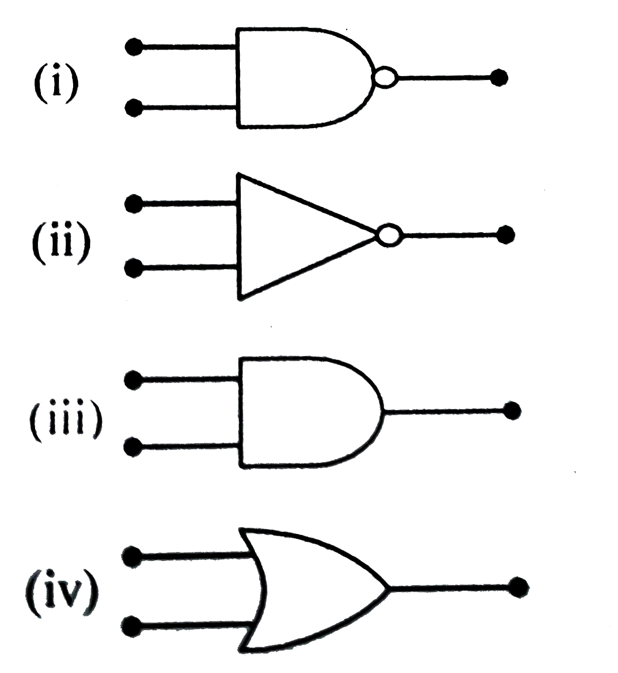
View SolutionThe symbolic representation of four logic gates are given in Fig.The logic symbol for OR, NOT and NAND gates are respectively

View SolutionThe symbolic representation of four logic gates are given below :

The logic symbols for OR, NOT and NAND gates are respectively :
View Solution
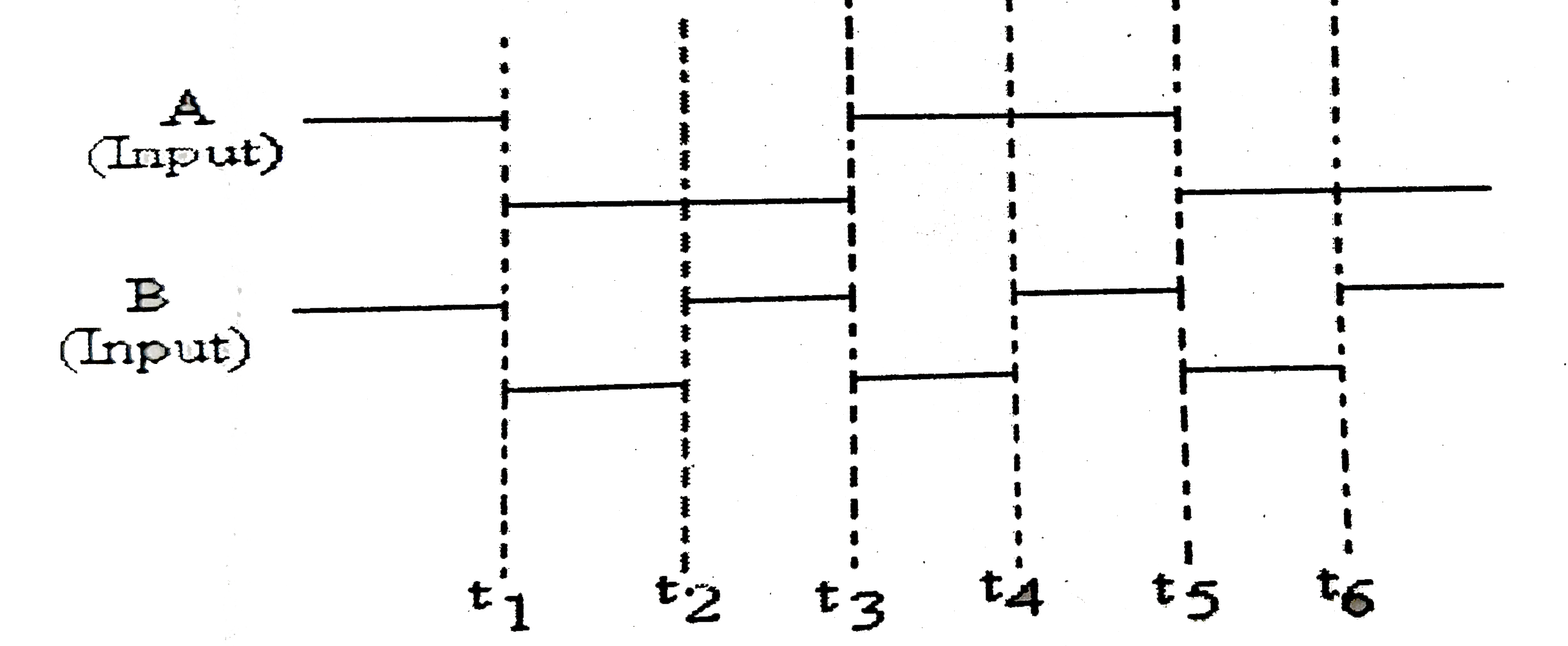
The give inputs A, B are fed to a 2-input NAND gate. Draw the output wave form of the gate.
View Solution

