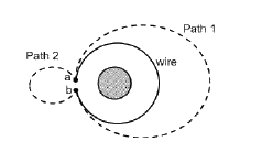
The circular wire in figure below encircles solenoid in which the magnetic flux is increasing at a constant rate out of the plane of the page.

The clockwise emf around the circular loop is ε0. By definition a voltammeter measures the volatage difference between the two pointws given by Vb−Va=−∫ba¯¯¯E.d¯s. We assume that a and b are infinitestically close to each other. The values of Vb−Va alon the path 1 and Va−Vb along the path 2, respectively are
−ε0,−ε0
−ε,0
−ε,εlo0
ε,ε0
Step by step video & image solution for The circular wire in figure below encircles solenoid in which the magnetic flux is increasing at a constant rate out of the plane of the page. The clockwise emf around the circular loop is epsilon0. By definition a voltammeter measures the volatage difference between the two pointws given by V_(b) - V_a = - int_(a)^(b) barE.d bars. We assume that a and b are infinitestically close to each other. The values of V_b - V_a alon the path 1 and V_a - V_b along the path 2, respectively are by Physics experts to help you in doubts & scoring excellent marks in Class 12 exams.
Updated on:21/07/2023Topper's Solved these Questions
- KVPY 2021Book:KVPY PREVIOUS YEARChapter:KVPY 2021Exercise:PART I (Chemistry)
Explore 2 Videos
- KVPY 2021Book:KVPY PREVIOUS YEARChapter:KVPY 2021Exercise:PART-I Physics
Explore 13 Videos
- KVPYBook:KVPY PREVIOUS YEARChapter:KVPYExercise:All Questions
Explore 415 Videos
- MOCK TEST 1Book:KVPY PREVIOUS YEARChapter:MOCK TEST 1Exercise:EXERCISE
Explore 23 Videos
Similar Questions
Knowledge Check
The circular wire in figure below encircles solenoid in which the magnetic flux is increasing at a constant rate out of the plane of the page.

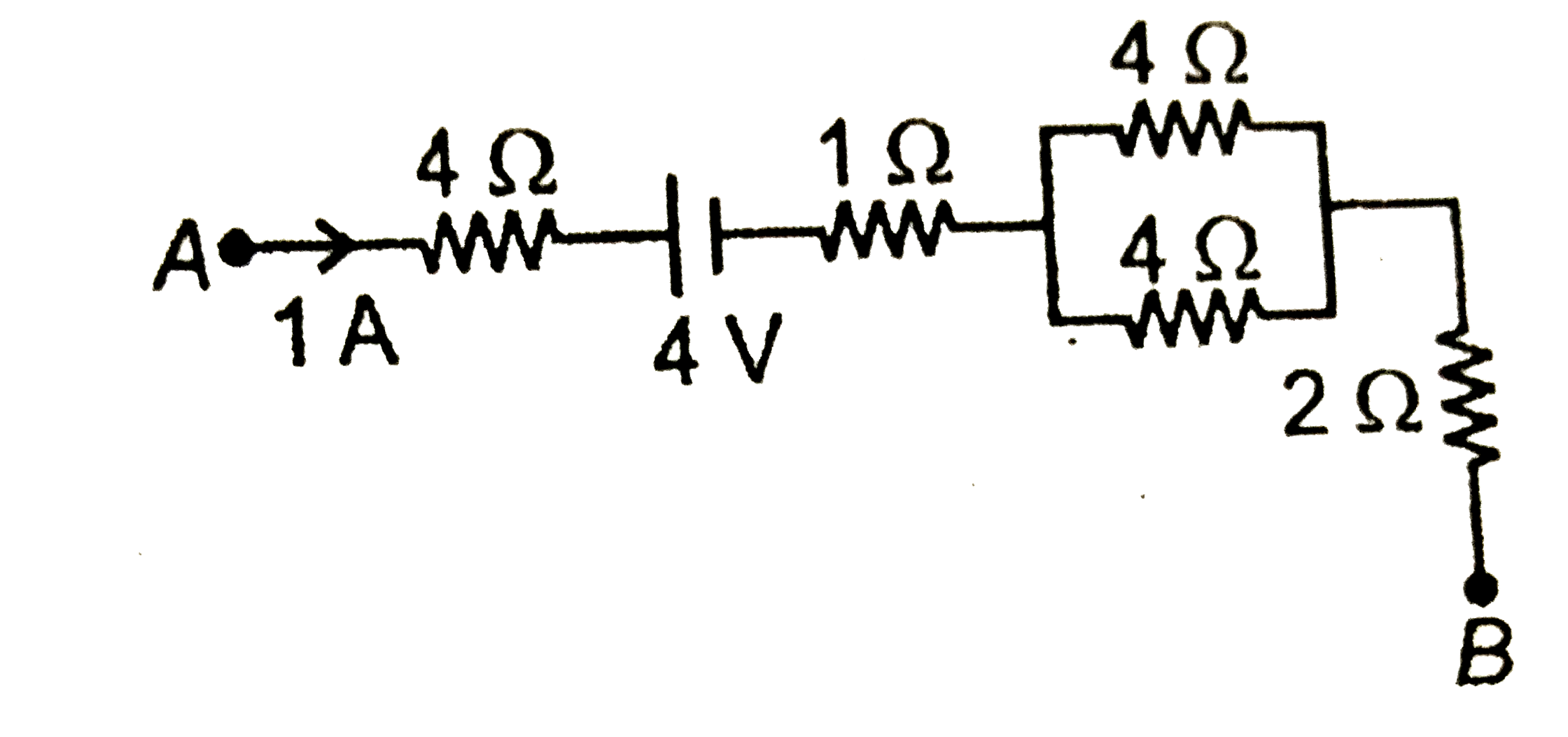
The clockwise emf around the circular loop is ε0. By definition a voltammeter measures the volatage difference between the two pointws given by Vb−Va=−∫ba¯¯¯E.d¯s. We assume that a and b are infinitestically close to each other. The values of Vb−Va alon the path 1 and Va−Vb along the path 2, respectively areA−ε0,−ε0B−ε0,0C−ε0,ε0Dε0,ε0The potential difference (VA−VB) between the point A and B as shown in the figure is
 A9VB8VC15VD13V
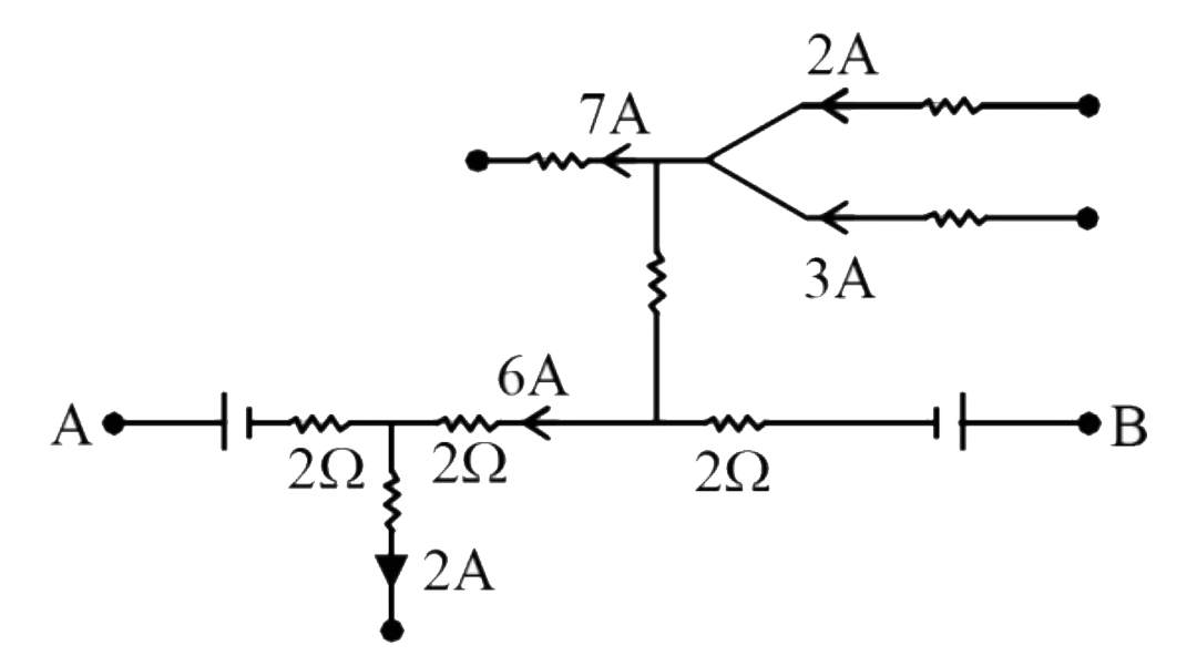
The potential difference (VA−VB) between the point A and B in the given figure is :
 A+6VB+9VC−3VD−8V
A conducting circular loop of radius r carries a constant current i. It is placed in a uniform magnetic field B such that B is parallel to the plane of the loop. The magnetic torque acting on the loop is-
View Solution
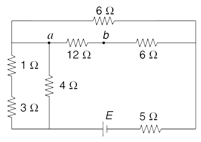
In the above circuit diagram emf of two batteries are equal , then the potential difference VA–VB between terminals A and B will be
View SolutionA conducting circular loop of radius r carries a constant current i. It is placed in a uniform magnetic field B such that B is perpendicular to the plane of the loop. The magnetic force acting on the loop is
View SolutionA conducting circular loop of radius r carries a constant current i.It is placed in a uniform magnetic field B such that B is perpendicular to the plane of the loop. The magnetic force acting on the loop is
View SolutionA steady current flows in a long wire. It is bent into a circular loop of one turn and the magnetic field at the center of the coil is B. If the same wire is bent into a circular loop of n turns, the magnetic field at the center of the coil is
View Solution


