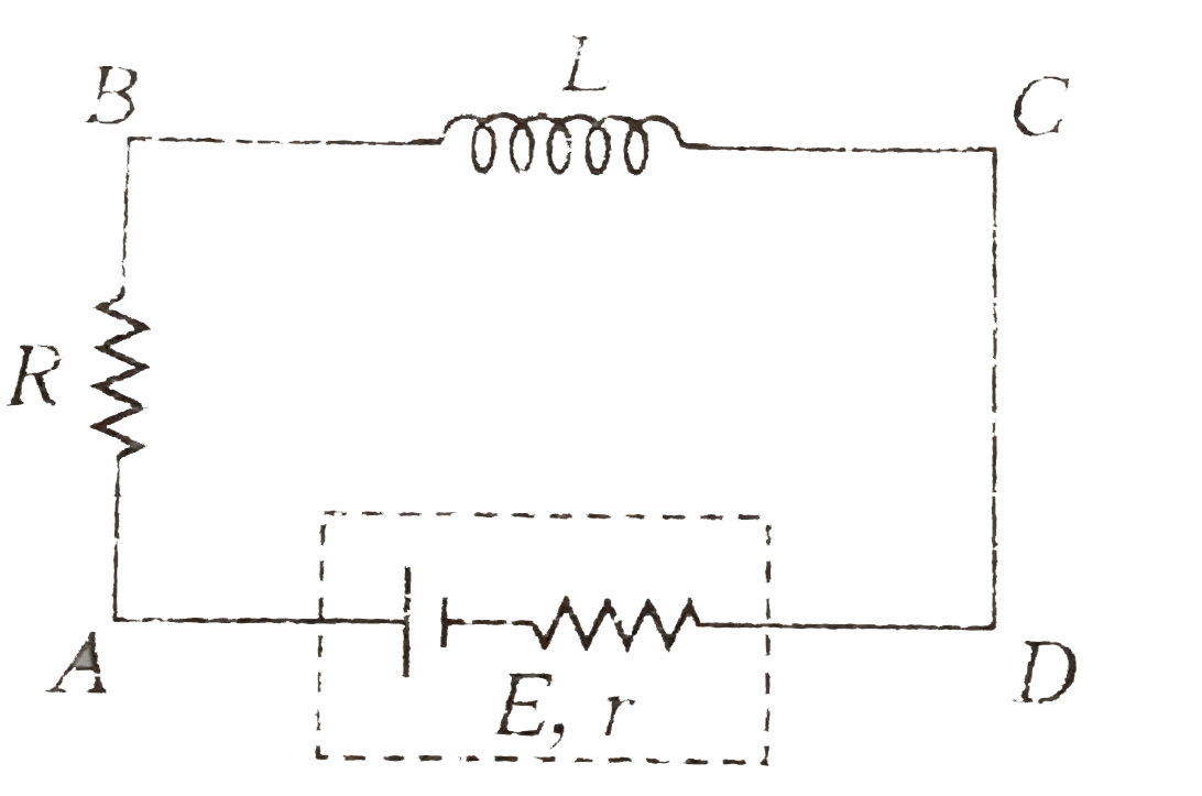
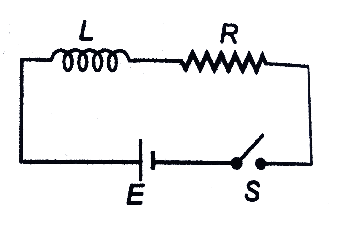
An LR circuit having L=4.0H,R=1.0Ωandε=6.0V is switched on at t=0. find the power dissipated in joule heating at t=4.0s.
To solve the problem step by step, we will follow the process of calculating the current in the LR circuit and then using that current to find the power dissipated due to Joule heating.
Step 1: Identify the parameters of the LR circuit
Given:
- Inductance L=4.0H
- Resistance R=1.0Ω
- Voltage ϵ=6.0V
- Time t=4.0s
Step 2: Calculate the steady-state current I0
The steady-state current I0 in an LR circuit is given by the formula:
I0=ϵR
Substituting the values:
I0=6.0V1.0Ω=6.0A
Step 3: Calculate the time constant τ
The time constant τ of an LR circuit is given by:
τ=LR
Substituting the values:
τ=4.0H1.0Ω=4.0s
Step 4: Calculate the current I(t) at t=4.0s
The current I(t) in the circuit at time t is given by:
I(t)=I0(1−e−tτ)
Substituting the values:
I(4)=6.0(1−e−4.04.0)=6.0(1−e−1)
Calculating e−1:
e−1≈0.3679
Thus:
I(4)=6.0(1−0.3679)=6.0×0.6321≈3.7926A≈3.8A
Step 5: Calculate the power dissipated in Joule heating
The power P dissipated in the resistor is given by:
P=I2R
Substituting the values:
P=(3.8A)2×1.0Ω=14.44W
Final Answer
The power dissipated in Joule heating at t=4.0s is approximately 14.44W.
---
Given:
- Inductance L=4.0H
- Resistance R=1.0Ω
- Voltage ϵ=6.0V
- Time t=4.0s
The steady-state current I0 in an LR circuit is given by the formula:
I0=ϵR
Substituting the values:
I0=6.0V1.0Ω=6.0A
The time constant τ of an LR circuit is given by:
τ=LR
Substituting the values:
τ=4.0H1.0Ω=4.0s
The current I(t) in the circuit at time t is given by:
I(t)=I0(1−e−tτ)
Substituting the values:
I(4)=6.0(1−e−4.04.0)=6.0(1−e−1)
Calculating e−1:
e−1≈0.3679
Thus:
I(4)=6.0(1−0.3679)=6.0×0.6321≈3.7926A≈3.8A
The power P dissipated in the resistor is given by:
P=I2R
Substituting the values:
P=(3.8A)2×1.0Ω=14.44W
The power dissipated in Joule heating at t=4.0s is approximately 14.44W.
Topper's Solved these Questions
- ELECTROMAGNETIC INDUCTIONBook:HC VERMA ENGLISHChapter:ELECTROMAGNETIC INDUCTIONExercise:Objective 1
Explore 11 Videos
- ELECTROMAGNETIC INDUCTIONBook:HC VERMA ENGLISHChapter:ELECTROMAGNETIC INDUCTIONExercise:Objective 2
Explore 10 Videos
- ELECTROMAGNETIC INDUCTIONBook:HC VERMA ENGLISHChapter:ELECTROMAGNETIC INDUCTIONExercise:Questions for short answer
Explore 9 Videos
- ELECTRIC FIELD AND POTENTIALBook:HC VERMA ENGLISHChapter:ELECTRIC FIELD AND POTENTIALExercise:Objective 2
Explore 7 Videos
- ELECTROMAGNETIC WAVESBook:HC VERMA ENGLISHChapter:ELECTROMAGNETIC WAVESExercise:Exercise
Explore 8 Videos
Similar Questions
An LR circuit has L= 1.0 H and R=20Ω. It is connected across an emf of 2.0 V at t=0. Find di/dt and Ldi/dt at t=50ms.
View SolutionIn an L C R circuit having L = 8 H, C = 0 5μF and R=100Ω in series, the resonance frequency in rad/s is
View SolutionAn LR circuit has L = 1.0 H R=20Ω. It is connected across an emf of 2.0V at t=0. Find didt at (a) t =100ms, (b) t =200 ms and (c ) t = 1.0 s.
View SolutionA resistor of resistance 100Ω is connected to an AC source ε=(12V)sin(250πs−1)t. Find the energy dissipated as heat during t=0 to t=1.0ms.
View SolutionIn a series RC circuit with an AC source, R=300Ω,C=25μF,ε0=50V and v=50πHz. Find the peak current and the average power dissipated in the circuit.
View SolutionAn LR combination is connected to an idal battery. If l = 10 mH, R = 2.0 Omega and epsilon = 2.0 V, how much time will it take for the current ot reach 0.63 A?
View SolutionIn a series LR circuit (L=3H,R=1.5Ω) and DC voltage =1V. Find current at T=2 seconds.
View SolutionIn the circuit shown in figure, E = 10 V, r = 1Ω,
R = 4Ω and L = 5H. The circuit is closed at time t = 0.
Then, match the following two columns.

Column IColumn IIA.VAD at t = 0p4VB.VBC at t = 0q8VC.VAB at t =∞r.0VD.VAD at t=∞s.10V
View SolutionIn the circuit shown in figure L=10H,R=5Ω,E=15V. The switch S is closed at t=0. At t=2s the current in the circuit is

View SolutionSwitch is closed at t=0 then the current in the circuit at t=L2R is
_PHY_E06_157_Q01.png)
View Solution