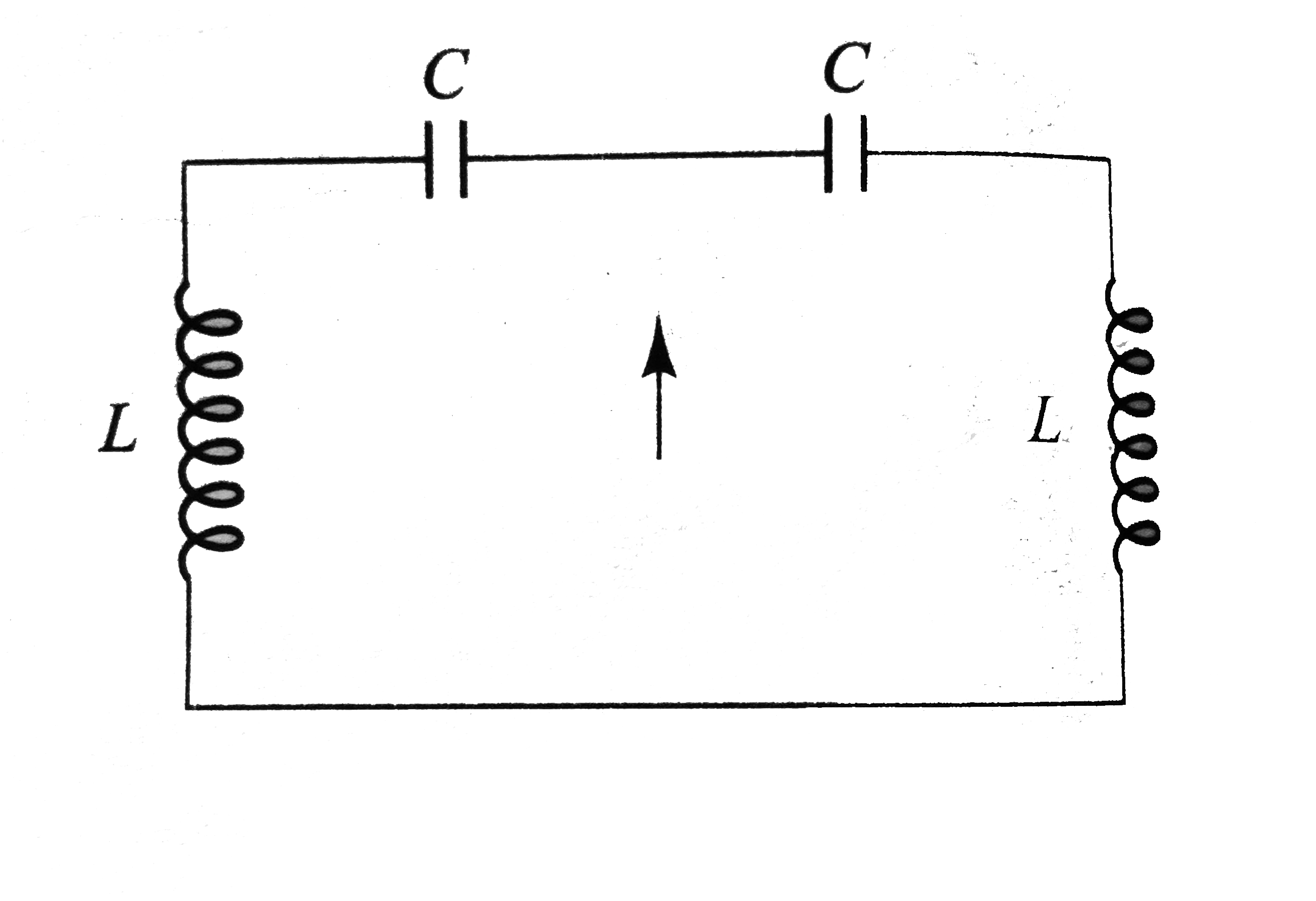
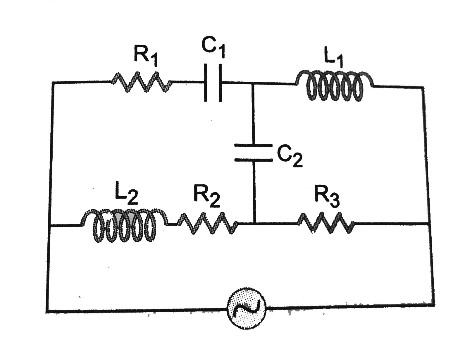
Draw the effective equivalent circuit of the circuit show in Fig. at very high frequencies and find the effective impedance.
Video Solution
Text Solution
The correct Answer is:A
We know that inductive reactance XL=2πfL
and capacitance reactance XC=12πfC
For very high frequencies (f→∞),XL→∞ and XC→0
When reactance of a circuit is infinite it will be considered as open circuit. When reactance of a circuit is zero it will be considered as short circuited.
So, C1,C2→ shorted and L1,L2→ opened.
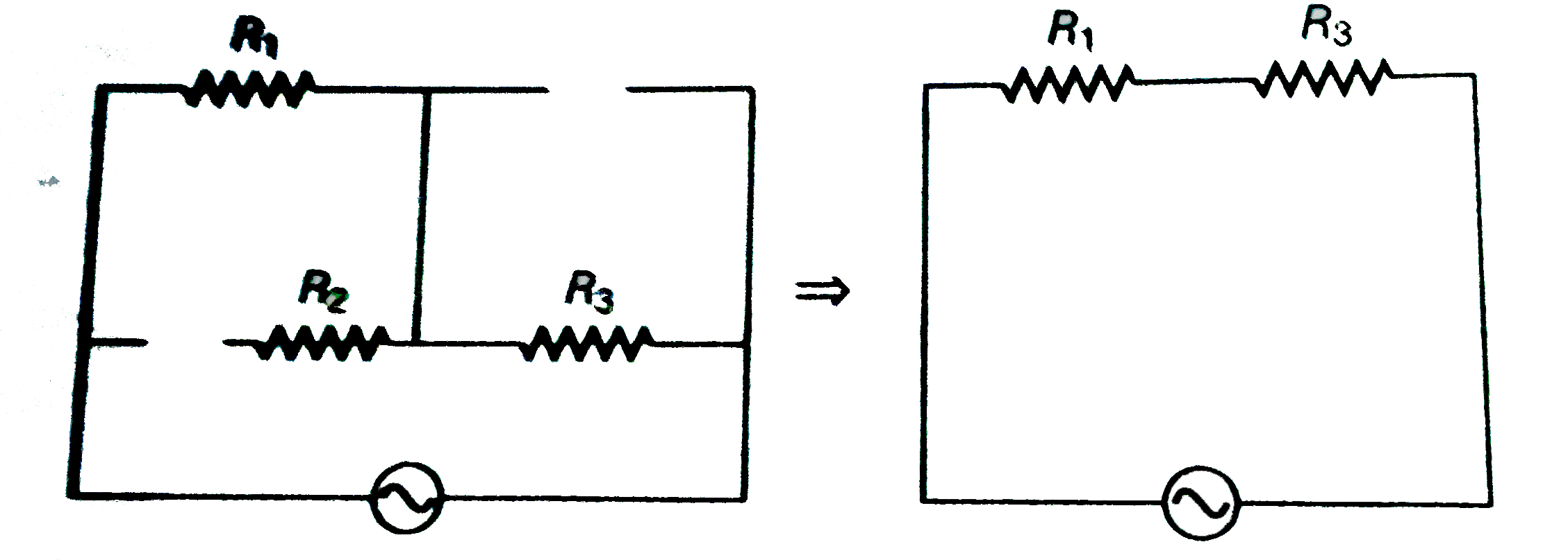
So, effective impedance =Req=R1+R3
|
Topper's Solved these Questions
- ALTERNATING CURRENTBOOK - NCERT EXEMPLAR ENGLISHCHAPTER - ALTERNATING CURRENTEXERCISE - Short Answer types questions
1 Video
- ALTERNATING CURRENTBOOK - NCERT EXEMPLAR ENGLISHCHAPTER - ALTERNATING CURRENTEXERCISE - Long Answe types Questions
5 Videos
- ALTERNATING CURRENTBOOK - NCERT EXEMPLAR ENGLISHCHAPTER - ALTERNATING CURRENTEXERCISE - Long Answe types Questions
5 Videos
- ATOMSBOOK - NCERT EXEMPLAR ENGLISHCHAPTER - ATOMSEXERCISE - Long Answer Type
6 Videos
Similar Questions
Knowledge Check
The circuit as shown in the figure is equivalent to
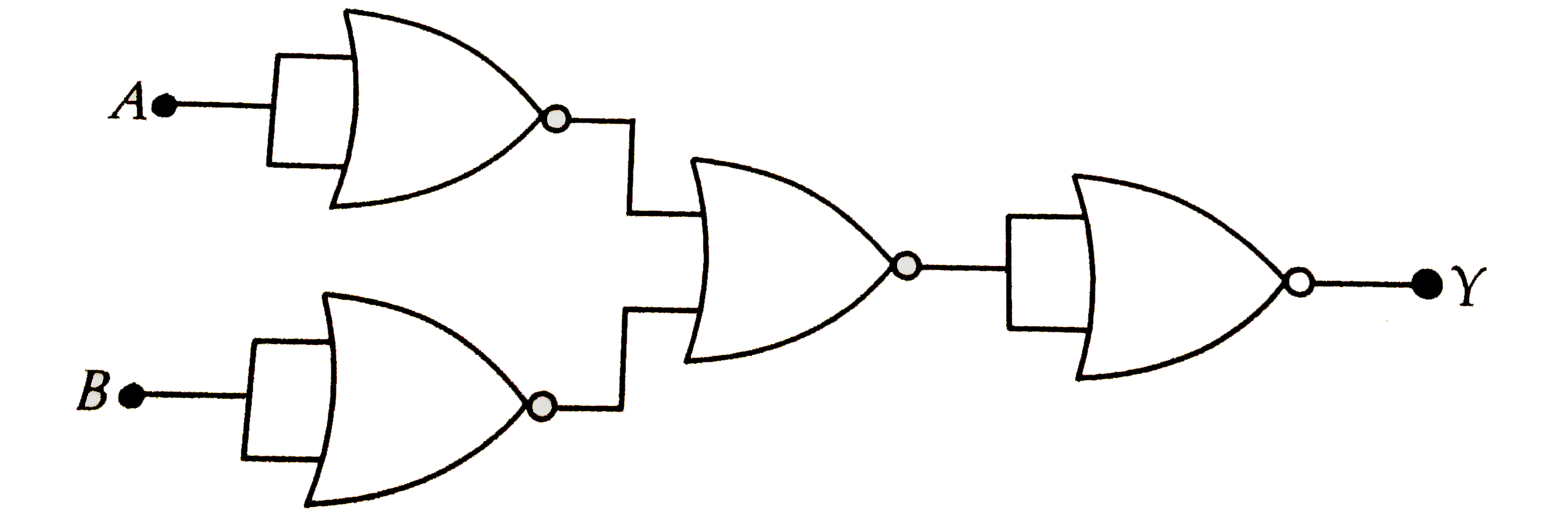 AAND gateBNOT gateCOR gateDNAND gate
The circuit is equivalent to

View SolutionThe circuit is equivalent to

View SolutionFind the current in each resistor in the circuit as shown in fig.
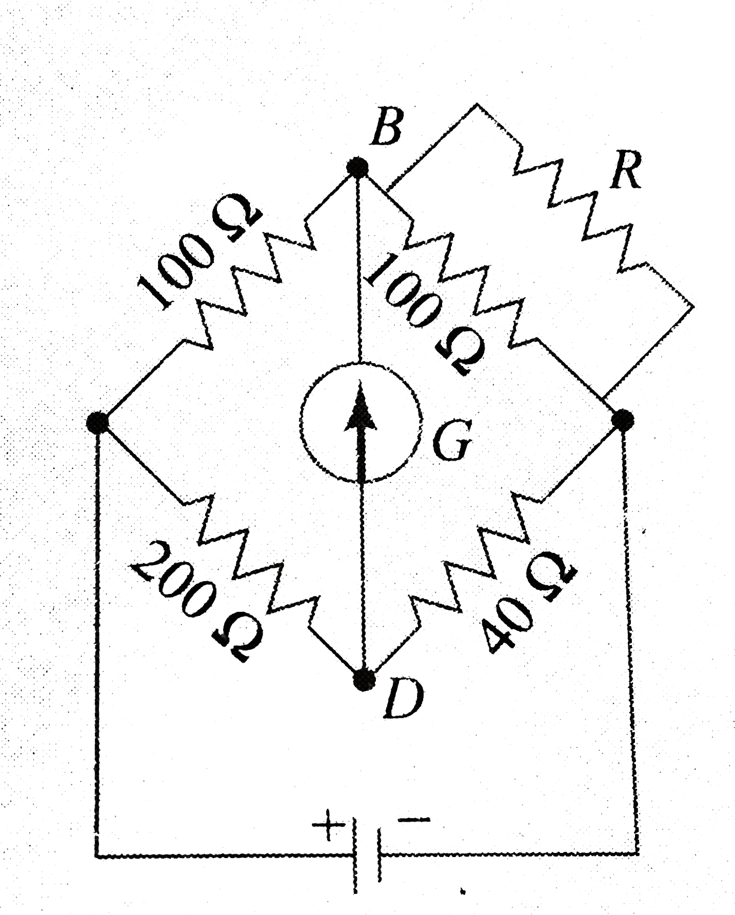
View SolutionCalculate equivalent resistance between A and B of the circuit shown in fig.
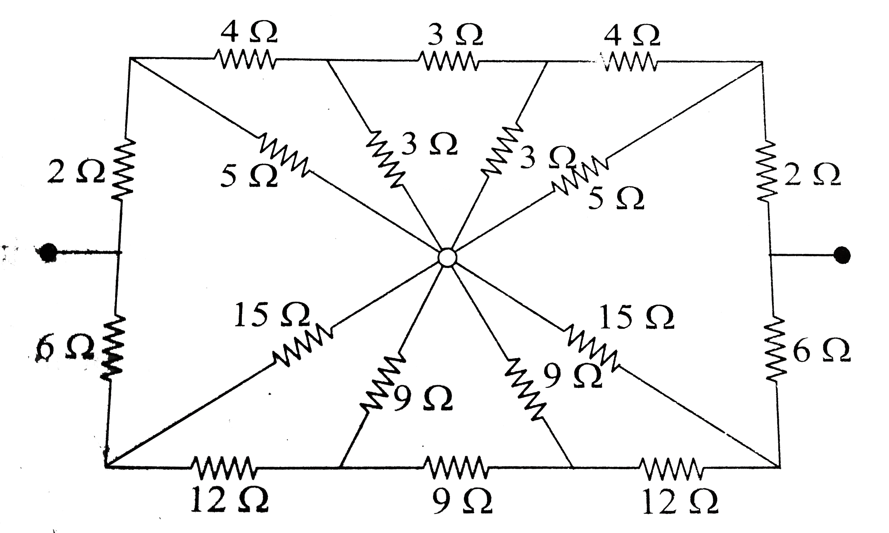
View SolutionFor the circuit shown in fig. the equivalent resistance between A and C is
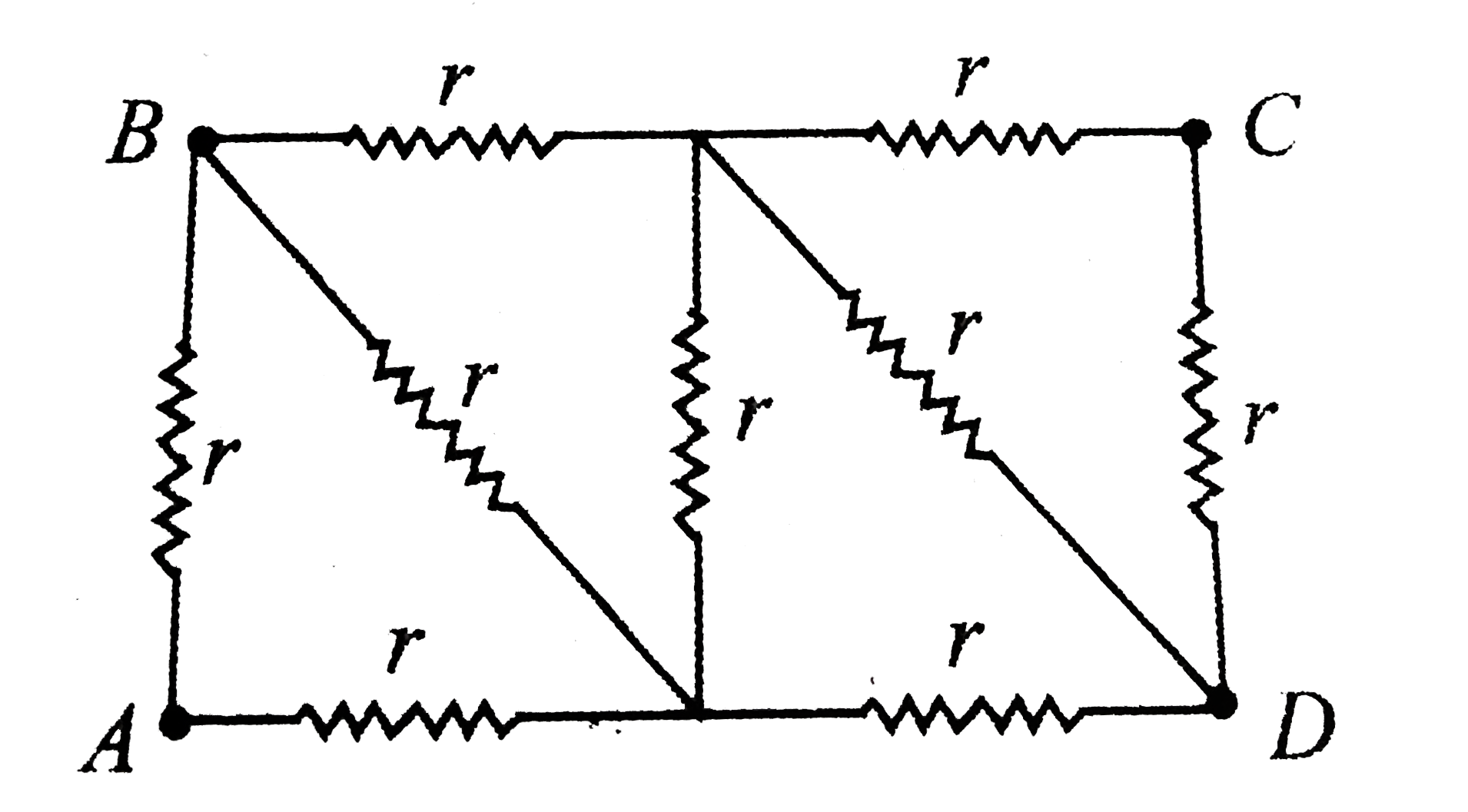
View SolutionCalculate the effective resistance between the points A and B in the circuit shown in Fig.
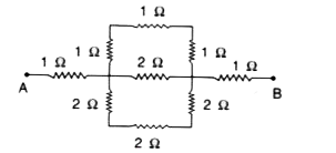
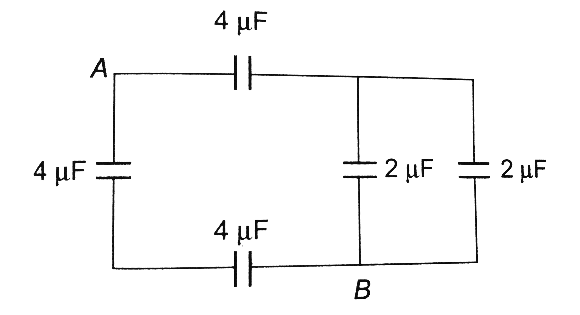
View SolutionIn the circuit as shown in the figure the effective capacitance between A and B is
View Solution
