Figure shows a series LCR circuit connected to a variable frequency 230 V source. L=5.0H,C=80μF,R=40Ω.
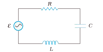
(a) Determine the source frequency which drives the circuit in resonance.
(b) Obtain the impedance of the circuit and the amplitude of current at the resonating frequency.
(c) Determine the rms potential drops across the three elements of the circuit. Show that the potential drop across the LC combination is zero at the resonating frequency.Solution in Gujrati
(a) 50rads−1
(b) 40Ω,8.1A
(c ) VLrms=1437.5V,VCrms=1437.5V,VRrms=230V
VLCrms=Irms=(ω0L−1ω0C)=0
Topper's Solved these Questions
Similar Questions
An LC circuit contains a 20 mH inductor and a 50 μF capacitor with an initial charge of 10 mC. The resistance of the circuit is negligible. Let the instant the circuit is closed be t = 0.
(a) What is the total energy stored initially? Is it conserved during LC oscillations?
(b) What is the natural frequency of the circuit?
(c) At what time is the energy stored
(i) completely electrical (i.e., stored in the capacitor)? (ii) completely magnetic (i.e., stored in the inductor)?
(d) At what times is the total energy shared equally between the inductor and the capacitor?
(e) If a resistor is inserted in the circuit, how much energy is eventually dissipated as heat?
View SolutionAn LC circuit contains a 20 mH inductor and a 50 μF capacitor with an initial charge of 10 mC. The resistance of the circuit is negligible. Let the instant the circuit is closed be t = 0.
(a) What is the total energy stored initially? Is it conserved during LC oscillations?
(b) What is the natural frequency of the circuit?
(c) At what time is the energy stored
(i) completely electrical (i.e., stored in the capacitor)? (ii) completely magnetic (i.e., stored in the inductor)?
(d) At what times is the total energy shared equally between the inductor and the capacitor?
(e) If a resistor is inserted in the circuit, how much energy is eventually dissipated as heat?
View SolutionAnswer the following questions, which help you understand the difference between Thomson’s model and Rutherford’s model better.
(a) Is the average angle of deflection of a-particles by a thin gold foil predicted by Thomson’s model much less, about the same, or much greater than that predicted by Rutherford’s model?
View SolutionA series LCR circuit connected to a variable frequency 230 V source has L = 5.0 H, C = 80 mu F , R = 40 Omega , Fig. (a) Determine the source frequency which drives the circuit in resonance. (b) Obtain the impedance of the circuit and amplitude of current at at resonating frequency. (c ) Determine the r.m.s. potential drops acorss the three elements the circuits. Show that the potential drop acorss the LC combination is zero at the resonating frequecny.
View SolutionFig 14.18 shows a series LCR circuit connected to a variable frequency 200 V source:
L=4.0H,C=100μF and R=40Ω.
(i) Calculate the resonant frequency of the circuit.
(ii) Obtain the impedance of the circuit and the amplitude of the current at resonating frequency.
(iii) Determine r.m.s. potential drop across L.
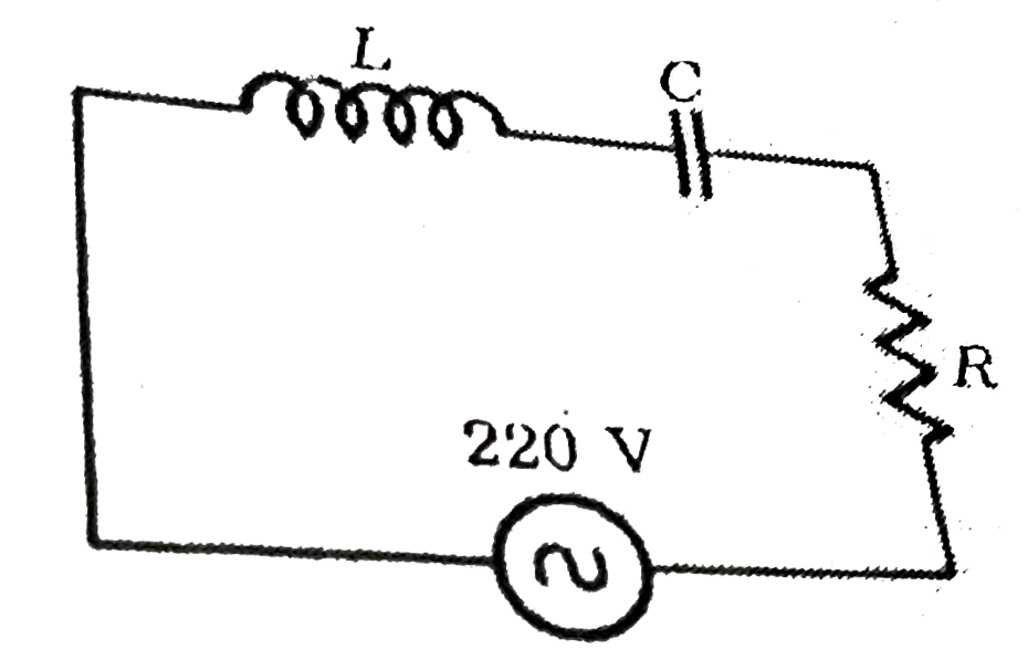
View SolutionFigure here, shows a series L-C-R circuit connected to a variable frequency 230 V source. L = 5.0H, C = 80 muF and r = 40 Omega (a) Determine the source frequency which drives the circuit in resonance. (b) Obtain the impedance of the circuit and the amplitude of current at the resonating frequency. (c) Determine the rms potential drops across the three elements of the circuit. show that the potential drop across the L-C combination is zero at the resonating frequency.
View SolutionFigure shows a series LCR circuit connected to a variable frequency 230 V source. L=5.0H,C=80μF,R=40Ω.

Determine the source frequency which drives the circuit in resonance.
View SolutionFigure shows a series LCR circuit connected to a variable frequency 230 V source. L=5.0H,C=80μF,R=40Ω.
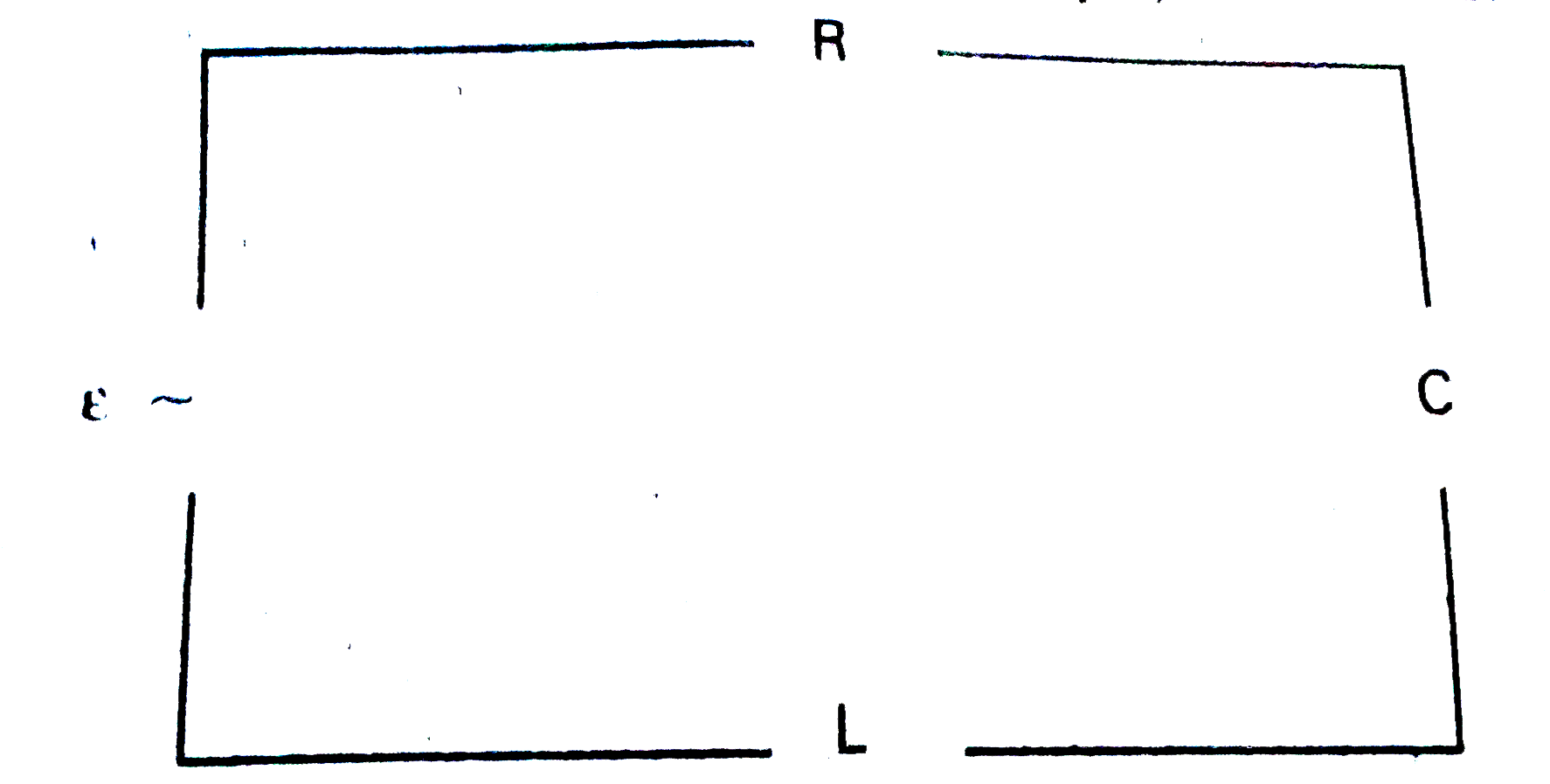
Obtain the impedance of the circuit and the amplitude of current at the resonanting frequency.
View SolutionFigure shows a series LCR circuit connected to a variable frequency 230 V source. L = 5.0 H, C = 80 mu F, R = 40 Omega . Determine the rms potential drops across the three elements of the circuit. Show that the potential drop across the LC combination is zero at the resonating frequency.
View SolutionFigure shows a series LCR circuit connected to a variable frequency 230 V source. L=5.0H,C=80μF,R=40Ω
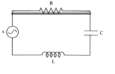
a. Determine the source frequency which drives the circuit in resonance
b. Obtain the impedance of the circuit and the amplitude of current at the resonating frequency.
c. Determine the rms potential drops across the three elements of the circuit. Show that the potential drop across the LC combination is zero at the rasonating frequency .
View Solutionएक श्रेणी LCR परिपथ में L=10.0H,C=40μF तथा R=60Omega को 240V वोल्ट के परिवर्ती आवृत्ति के प्रत्यावर्ती धारा स्त्रोत से जोड़ा गया है । गणना कीजिए -(i ) स्त्रोत की कोणीय आवृत्ति जो परिपथ को अनुनाद की अवस्था में लाती है ,(ii ) अनुनादी आवृत्ति पर धारा , (iii ) प्रेरक के सिरों के बीच अनुनाद की दशा में वर्ग - माध्य - मूल विभव पतन ।
View SolutionFigure shows a series LCR circuit connected to a variable frequency 230 V source. L = 5.0 H, C = 80muF, R = 40 Omega . (a) Determine the source frequency which drives the circuit in resonance. (b) Obtain the impedance of the circuit and the amplitude of current at the resonating frequency. (c) Determine the rms potential drops across the three elements of the circuit. Show that the potential drop across the LC combination is zero at the resonating frequency.
View SolutionFigure shows a series LCR circuit connected to a variable frequency 230 V source. L=5.0H,C=80μF,R=40Ω.
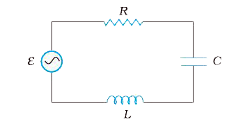
(a) Determine the source frequency which drives the circuit in resonance.
(b) Obtain the impedance of the circuit and the amplitude of current at the resonating frequency.
(c) Determine the rms potential drops across the three elements of the circuit. Show that the potential drop across the LC combination is zero at the resonating frequency.
View SolutionFigure shows a series LCR circuit connected to a variable frequency 230 V source. L=5.0H,C=80μF,R=40Ω.

Determine the source frequency which drives the circuit in resonance.
View SolutionA series LCR circuit connected to a variable frequency 230 V source has L = 5.0 H, C = 80 mu F , R = 40 Omega , Fig. (a) Determine the source frequency which drives the circuit in resonance. (b) Obtain the impedance of the circuit and amplitude of current at at resonating frequency. (c ) Determine the r.m.s. potential drops acorss the three elements the circuits. Show that the potential drop acorss the LC combination is zero at the resonating frequecny.
View Solution
