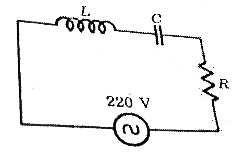
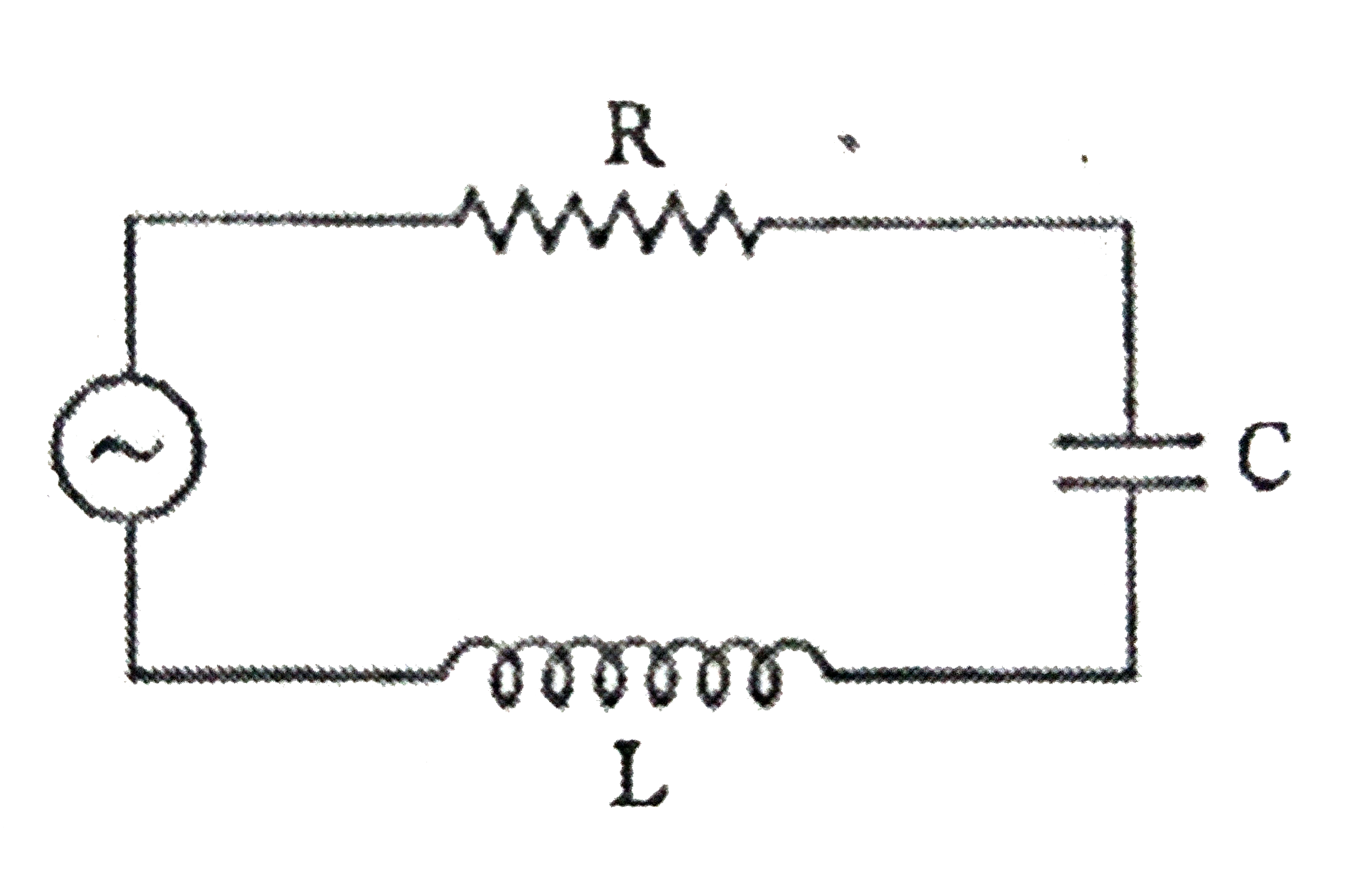
Fig 14.18 shows a series LCR circuit connected to a variable frequency 200 V source:
L=4.0H,C=100μF and R=40Ω.
(i) Calculate the resonant frequency of the circuit.
(ii) Obtain the impedance of the circuit and the amplitude of the current at resonating frequency.
(iii) Determine r.m.s. potential drop across L.
Step by step video & image solution for Fig 14.18 shows a series LCR circuit connected to a variable frequency 200 V source: L=4.0H, C=100 muF and R=40 Omega. (i) Calculate the resonant frequency of the circuit. (ii) Obtain the impedance of the circuit and the amplitude of the current at resonating frequency. (iii) Determine r.m.s. potential drop across L. by Physics experts to help you in doubts & scoring excellent marks in Class 12 exams.
Updated on:21/07/2023Topper's Solved these Questions
Similar Questions
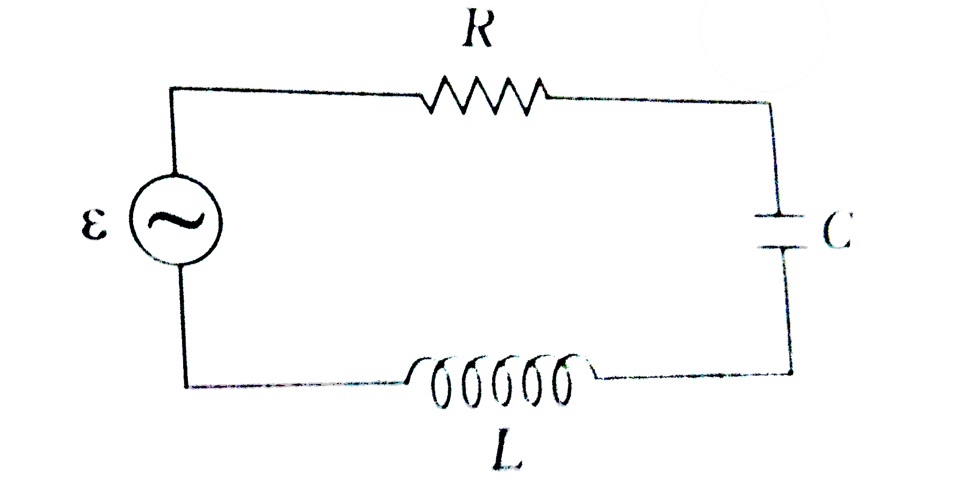
Figure here, shows a series L-C-R circuit connected to a variable frequency 230 V source. L = 5.0H, C = 80μF and r =40Ω
(a) Determine the source frequency which drives the circuit in resonance.
(b) Obtain the impedance of the circuit and the amplitude of current at the resonating frequency.
(c) Determine the rms potential drops across the three elements of the circuit. show that the potential drop across the L-C combination is zero at the resonating frequency.
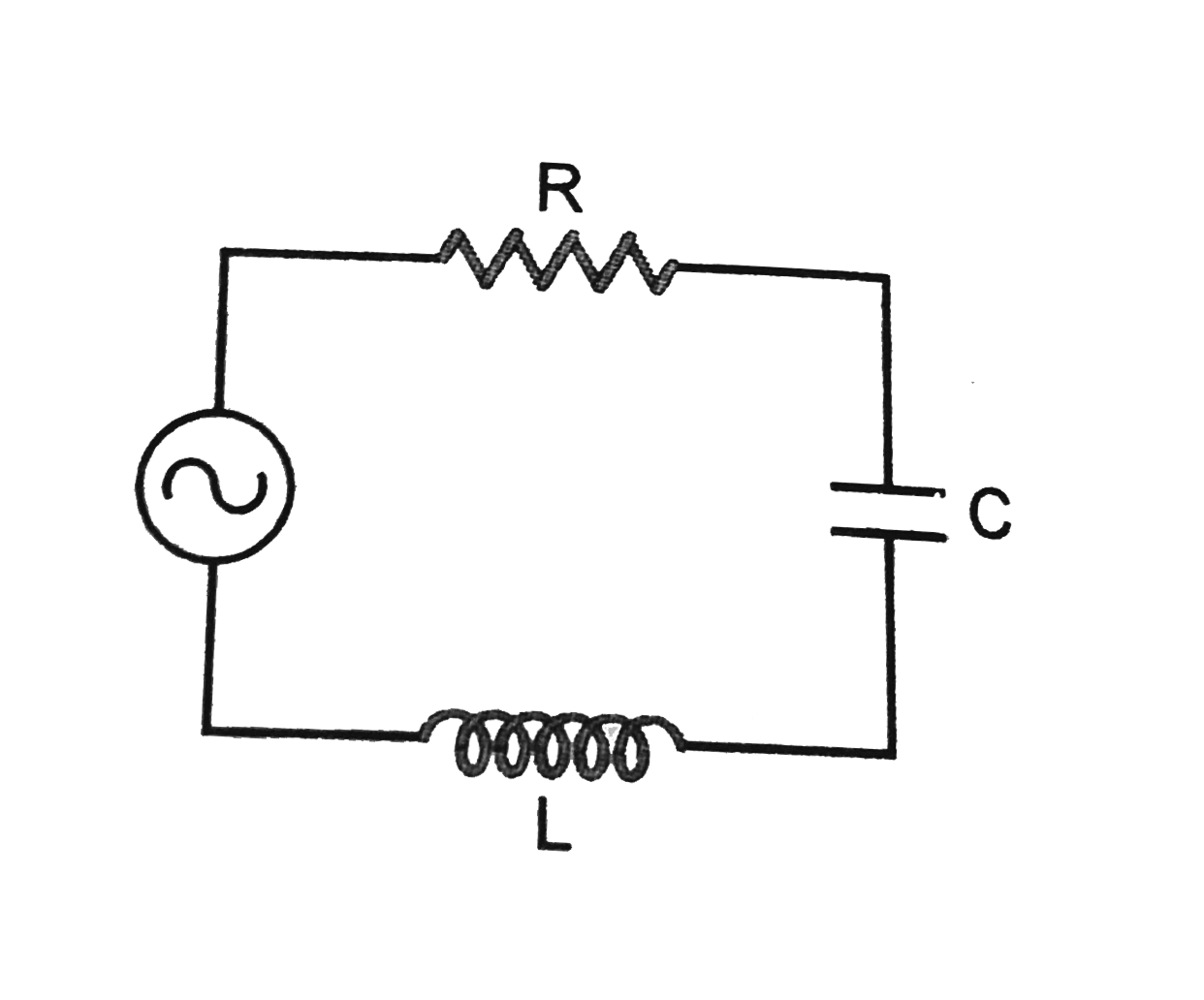
View SolutionA series LCR circuit connected to a variable frequency 230 V source has L = 5.0 H, C=80μF, R=40Ω, Fig.
(a) Determine the source frequency which drives the circuit in resonance.
(b) Obtain the impedance of the circuit and amplitude of current at at resonating frequency.
(c ) Determine the r.m.s. potential drops acorss the three elements the circuits. Show that the potential drop acorss the LC combination is zero at the resonating frequecny.
View Solution
Knowledge Check
Figure shows a series LCR circuit connected to a variable frequency 230 V source.

The source frequency which drives the circuit the circuit in resonance isA4 HzB5 HzC6 HzD8 HzAn LCR series circuit contains L=8H,C=0.5μF and R=100Ω The resonant frequency of the circuit is .
A1000πHzB500πHzC250πHzD125πHzIn the given figure , a series L-C-R circuit is connected to a variable frequency source of 230 V . The impedance and amplitude of the current at the resonating frequency will be
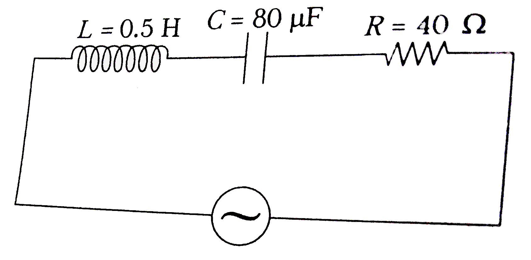 A20Ω and 4.2 AB30Ω and 6.9 AC25Ω and 5.8 AD40Ω and 5.75 A
A variable frequency 230 V alternating voltage source is connected across a series combination of L=5.0H,C=80μF and R=40Ω
(i) Calculate the angular frequency fo the source which drives the circuit in resonance.
(ii) Obtain r.m.s. the impedance of the circuit and amplitude of current at resonance frequency
(iii) Obtain r.m.s. potential drop across the three elements of the circuit at resonating frequency.
(iv) How do you explain the observation that the algerbraic sum of voltages across the three elements obtained is greater than the supplied voltage.
View SolutionThe figure shows a series LCR circuit with L=10.0H2,C=40μF,R=60Ω connected to a variable frequency 240 V source. Calculate
(i) The angular frequency of the source which drives the circuit at resonance.
(ii) The current at the resonating frequency.
(iii) The rms potential drop across the capacitor at resonance.
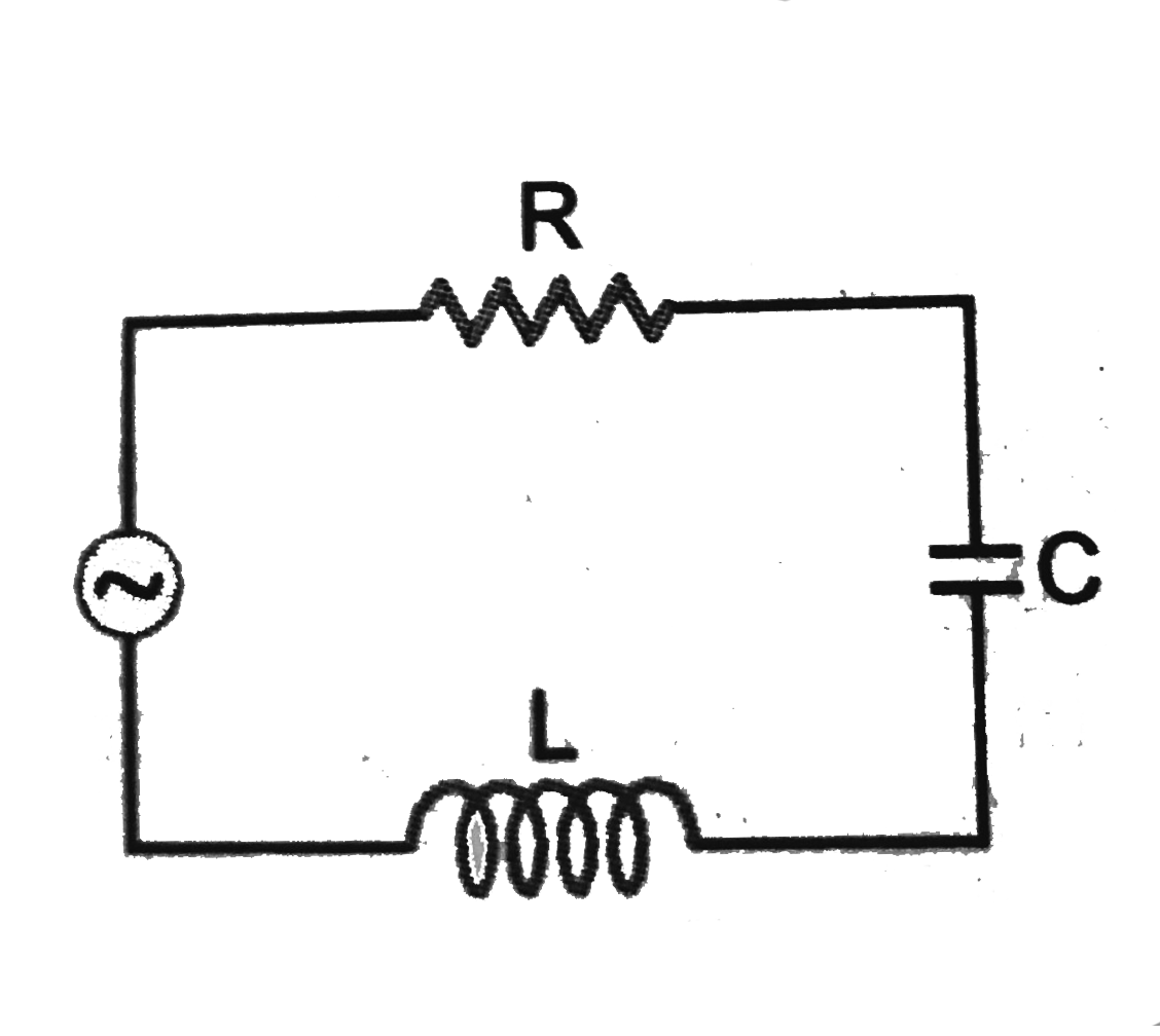
View SolutionFig. shows series LCR circuit with L=5.0H,C=80μF,R=40Ω connected to a variable frequency 240 V source. Calculate
(i) the angular freuquency of the source which drives the circuit at resonance.
(ii) Current at the resonanting frequency.
(iii) the rms pot. drop across the capacitor at resonance.
View SolutionA series LCR circuit with L=4.0h,C=100μF and R=60Ω is connected to a varialbe frequency 240 V source. Calcalate
(i) angular frequency of the source which drives the circuit in resonace,
(ii) current at the resonating frequency,
(iii) rms potential drop across the inductro at resonance.
View SolutionIn a series L-C-R circuit shown in the figure , what is the resonance frequency and the current at the resonating frequency?
View Solution
