In Fig. 27-37, the ideal batteries have emfs ε1=12.0Vand=ε2=0.500ε1 and the resistances are each 4.00Ω. What is the current in (a) resistance 2 and (b) resistance 3? 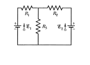
The correct Answer is:0A;(b)1.5A
Step by step video, text & image solution for In Fig. 27-37, the ideal batteries have emfs epsi_(1)= 12.0 V and = epsi_(2)=0.500 epsi_(1) and the resistances are each 4.00 Omega. What is the current in (a) resistance 2 and (b) resistance 3? by Physics experts to help you in doubts & scoring excellent marks in Class 12 exams.
Topper's Solved these Questions
- BOOK - RESNICK AND HALLIDAYCHAPTER - CIRCUITSEXERCISE - Practice Questions (Single Correct Choice Type)33videos
CIRCUITS
- BOOK - RESNICK AND HALLIDAYCHAPTER - CIRCUITSEXERCISE - Practice Questions (More than One Correct Choice Type)12videos
CIRCUITS
- BOOK - RESNICK AND HALLIDAYCHAPTER - CIRCUITSEXERCISE - Checkpoints7videos
CIRCUITS
- BOOK - RESNICK AND HALLIDAYCHAPTER - CENTER OF MASS EXERCISE - Practice Questions (Integer )4videos
CENTER OF MASS
- BOOK - RESNICK AND HALLIDAYCHAPTER - CIRCULAR MOTIONEXERCISE - CHECK POINTS6videos
CIRCULAR MOTION
Similar Questions
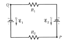
In Fig 27-56, the ideal batteries have emf emf12=200Vandε2=50V and the resistances are R1=3.0ΩandR2=2.0Ω. If the potential at P is 100 V, what is at at Q?
 View Solution
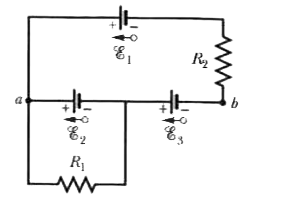
In Fig. 27-63, R1=100Ω,R2=50Ω, and the ideal batteries have emfs, ε1=6.0V,ε2=10V,andε3=4.0V. Find (a) the current in resistor 1, (b) the current in resistor 2, and (c) the potential difference between points a and b.
 View Solution
Knowledge Check
- Question 1 - Select One

Two batteries of emf ε1andε2(ε2>ε1) and internal resistance r1andr2 respectively are connected in parallel as shown in figure.AThe equivalent emf εeq of the two cells is between ε1andε2, i.e., ε1<εeq<ε2Bthe equivalent emf εeq is smaller than ε1CThe εeq is given by εeq=ε1+ε2 always.Dεeq is independent of internal resistance r1andr2. - Question 2 - Select One
Two batteries of emf ε1 and ε2(ε2>ε1) and internal resistances r_1 and r2 respectively are connected in parallel as shown in Fig. Then
 Athe equivalent emf εeq of the two cells is betweenε1 and ε2 i.e., ε1<εeq<ε2Bthe equivalent emf εeq is smaller than ε1Cthe εeq is given by εeq=ε1+ε2 always .Dεeq is independent of internal resistances r1 and r2
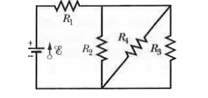
In Fig. 27-40, R1=100Ω,R2=R3=50.00Ω,R4=75.0Ω, and the ideal battery has emf ε=12.0V. (a) What is the equivalent resistance? What is i in (b) resistance 1, (c) resistance 2,(d) resistance 3, and (e) resistance 4?
 View Solution
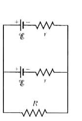
In Fig. 27-38, two batteries with an emf ε=12.0V and an internal resistance r=0.500 Ω are connected in parallel across a resistance R. (a) For what value of R is the dissipation rate in the resistor a maximum? (b) What is that maximum? and (c) what is the total dissipation rate in the batteries? In terms of r, what are (d) the effective R (internal) resistance of the two-battery system and (e) the resistance R that is required to maximize the dissipation rate? This is a general result.
 View Solution
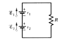
In Fig. 27-51. battery 1 has emf ε1=12.0V and internal resistance r1=0.025Ω and battery 2 has emf2=12.0V and internal resistance r2=0.012Ω. The batteries are connected in series with an external resistance R. (a) What R value makes the terminal-to-terminal potential difference of one of the batteries zero? (b) Which battery is that?
 View Solution
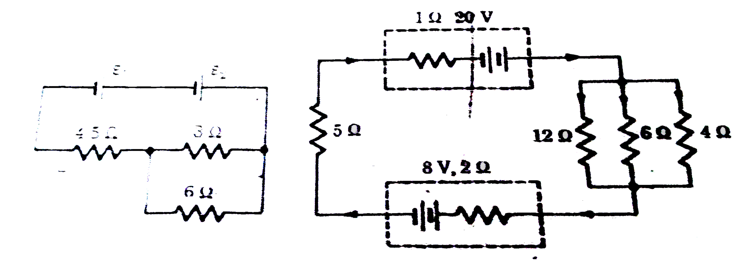
In the circuit shown in Fig. 4.68, the cells ε1 and ε2 have emf's of 4 V and 8 V and internal resistances of 0.5Ω and 1Ω respectively. Calculate the current in each resistance.
 View Solution
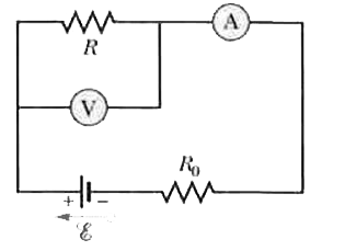
In Fig 27-53, a voltmeter of resistance Rv=300Ω and an ammeter of resistance RA=3.00Ω are being used to measure a resistance R in. a circuit that also contains a resistance R0=100Ω and an ideal battery of emf ε=28.5V. Resistance R is given by R=V//i where V is the voltmeter reading and i is the current in resistance R. However, the ammeter reading is not i but rather i', which is i plus the current through the voltmeter. Thus, the ratio of the two meter readings is not R but only an apparent resistance R'=V/I'. If R=85.0Ω what are (a) the ammeter reading. (b) the voltmeter reading, and (c) R' (d) If Rv is increased does the difference between R' and R increase, decrease or on the same?
 View Solution
The emf and resistances in the circuit of Fig 27-8a have the following values:
ε1=4.4V.ε2=2.1V,
r1=2.3Ω,r2=1.8Ω,R=5.5Ω
(a) What is the current I in the circuit?
(b) What is the potential difference between the terminals of battery 1 in Fig. 27 8a?View Solution
